Data Quality
Continuum image quality
All released continuum multi-frequency synthesis images have passed validation, ensuring that they meet the resolution requirements, minimum sensitivity requirements, and have no significant image artifacts, as described in “Validation of processed data products: Continuum”.
The noise values for all released continuum images are shown in Fig. 14. The left panel shows the noise distribution on the inner part of image (inner hereafter) where many sources are detected. On the right panel the noise of the outer part (outer hereafter), which is typically source-free, is considered (see “Validation of processed data products: Continuum” for more details). The median values (41.4 and 36.1 uJy, respectively) are indicated by the solid lines. The dashed lines and numbers in parentheses indicate the noise values that bound 68% of all values around the median. The median value of the inner noise is slightly larger; this is because the inner part of the image has sources and may still have minor artifacts. The outer noise represents the theoretical best that can be achieved with perfect imaging. The median outer noise is 36.1 microJy/beam and the best achievable (5th percentile) is 29.3 microJy per beam.
The noise values skew to higher values from the median. This is likely because some images may still have minor imaging artifacts. Any issue affecting image quality will only ever increase the noise of an image.
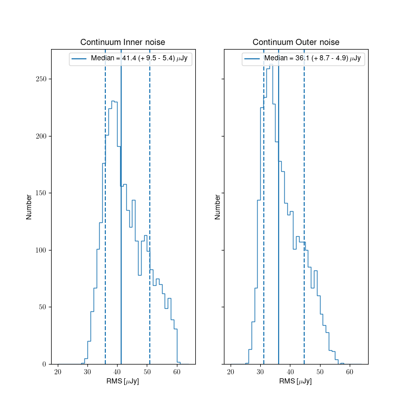
Fig. 14 Noise distribution for all relased images in the inner (left) and outer (right) part of the continuum images.
Polarization data quality
All processed data products are released based on the continuum validation (see “Released processed data products”). Thus, some polarization images and cubes may be released that do not pass their own validation. However, this is a small number of images/cubes and they may still be useful (see “Validation of processed data products: Polarization” for more details).
Fig. 15 shows the distribution of inner and outer noise for the Stokes V mfs images. Both all released images (3374) and only those that pass validation (3198) are shown. Very few polarization images fail the polarization validation after passing the continuum validation. This is to be expected as the validation criteria are very similar and the continuum and Stokes V mfs images should generally have similar quality to each other. There is no appreciable difference in the noise distribution between all released images and those that pass validation.
The same qualitative trends are present as for the continuum noise; the outer noise is lower than the inner, and the distribution of noise values is skewed to higher noise values, due to the presence of low level artifacts that increase the noise. Overall, the noise in the polarization images is lower than the continuum; this is likely because the Stokes V images are essentially empty.
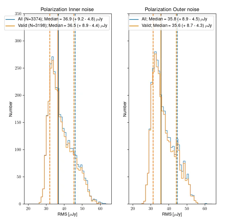
Fig. 15 Noise distribution for all relased (blue) and valid (orange) Stokes V multi frequency images, in the case of the inner (left) and outer (right) part.
Line data Quality
Line cubes are released for a beam if the continuum image passes validation; thus some of the line cubes may fail their validation. The line cubes are classified as “good”, “okay” or “bad” depending on the severity of the artefacts in the line data, as detailed in “Validation of processed data products: HI”.
Fig. 16 shows the distribution of noise for cubes 0, 1 and 2. All released cubes are shown, plus split separately into the good, okay, bad categories. The median noise over all released cubes is 1.62 mJy/bm. The median noise decreases slightly as the cubes increase in frequency; this is consistent with the RFI environment being worse at lower frequencies. As is to be expected, the median noise for good cubes is better than for the okay cubes, which are better than the bad cubes. The best achievable noise (5th percentile, cube 2, only good) is 1.32 mJy/beam.
As with the continuum and polarization noise distributions, the distribution has a longer tail to higher noise values; this is because image artifacts and bad frequency ranges will only ever increase the noise.
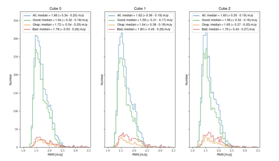
Fig. 16 Noise distribution for all relased (blue), Good (green), Okay (orange) and bad (red) HI line cubes for cube 0, 1 and 2.
Data quality per compound beam
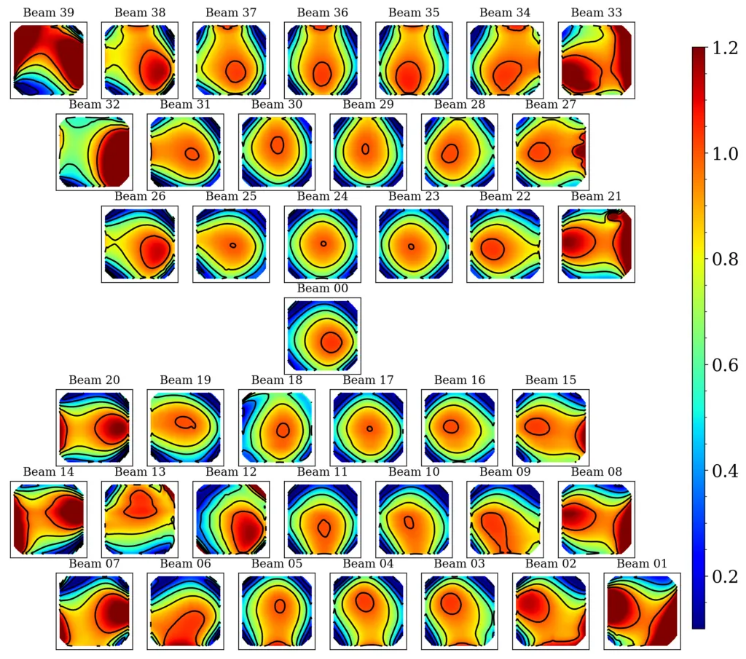
The above views of data quality combine all released observations, across different compound beams. However, the behavior of different compound beams is not identical. Specifically, the outer compound beams illuminate the edge of the field of view and thus may be expected to have a reduced sensitivity. For reference, Fig. 17 shows the compound beam layout, with colors indicating the expected sensitivity based on the forward gain of an Apertif phased-array feed (PAF).
Fig. 18 shows the normalized average noise (over all continuum images) in the compound beam layout. The beams on the edge of layout have higher average noise values, consistent with the picture that the overall sensitivity falls off. Fig. 19 quantifies this by showing the normalized noise as a function of distance from the pointing center of the PAF; the increased noise values track with distance.
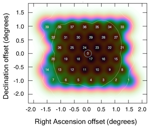
Fig. 17 The compound beam layout for Apertif. Blue is at about the 50% level; transition between black/brown to green is at about the 85% level.
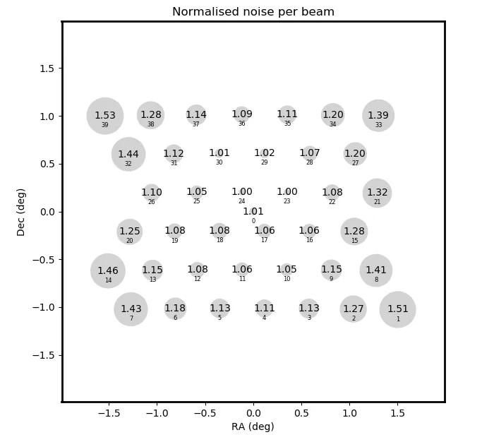 Fig. 18 The normalized average continuum noise per compound beam, shown in the compound beam layout. Compound beams closer to the edge have larger average noise values.
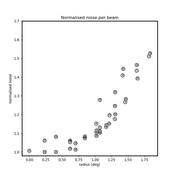 Fig. 19 The normalized continuum noise of each compound beam (labeled points) as a function of distance from pointing center of the PAF. The pattern of increased noise scales with distance from center of the PAF.
Released processed data products
The processed data products are of the most immediate scientific interest. Only processed data products which pass validation are considered for release. Specifically, we require the continuum multi-frequency synthesis (mfs) image to pass the validation outlined in “Validation of processed data products: Continuum”. In that case, all processed data products are released for that beam of a given observation. It may be the case that the polarization or line products do not pass their validation (see respective sections in “Validation of processed data products”). In this case, these data products are flagged in the quality assessment columns of the VO tables (see User Interfaces).
The sections below provide a brief look at the released data products for continuum, polarization and line. The separate section “Data quality” provides a view of the data quality of these released data products.
Released continuum data products
The main continuum data product is the multi-frequency synthesis continuum image. The resolution is better than 15′′×15′′/sin(δ) (requirement of validation). The median noise value is ~40 uJy/beam.
The table containing all observation / beam combinations that pass continuum validation, along with all the metrics used in continuum validation (described in ”Validation of processed data products: Continuum ”) can be exported using the VO infrastructure, more details are provided in section “User Interfaces”.
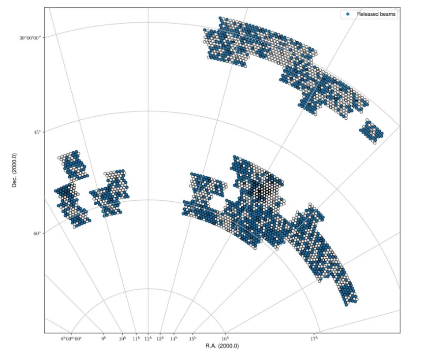
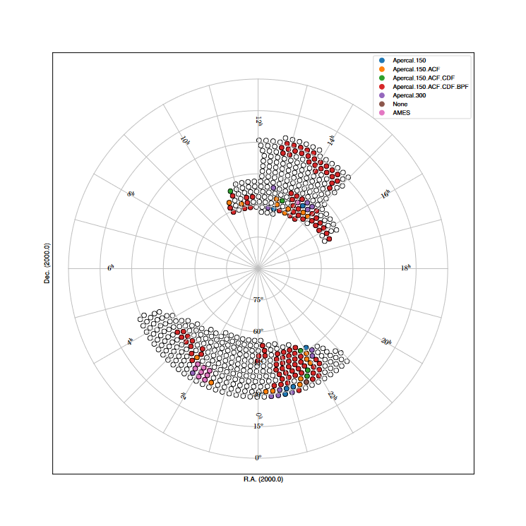
Fig. 20 The spring sky coverage of released beams based on the continuum validation.
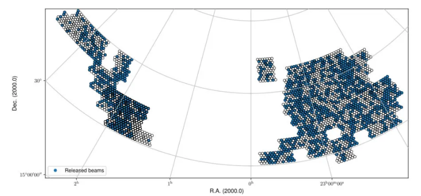
Fig. 21 The fall sky coverage of released beams based on the continuum validation.
Released polarization data products
The polarized data products include a Stokes V multi-frequency synthesis image and Stokes Q&U cubes. The polarized data products are only released if the continuum validation is passed but the polarization products may not pass their own validation (see section “Validation of processed data products: Polarization”). The Stokes V images and Q/U cubes are validated separately, and their validation state is clearly given in the User Interfaces.
A table of all released beams with the line validation status (“G”ood, “O”kay, or “B”ad) for cubes 0-2 (given by the columns “cube?_qual”), plus the metrics used for the line validation (described in HI validation) can be exported using the VO infrastructure, more details are provided in section “User Interfaces”.
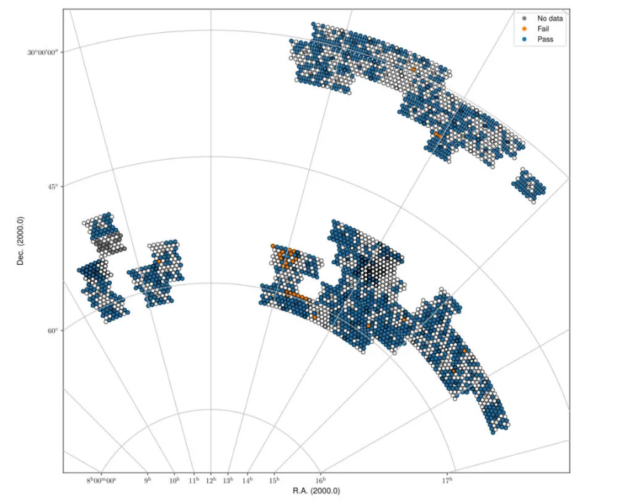
Fig. 22 Spring sky view of the released QU cubes, color-coded by whether they pass validation or not.
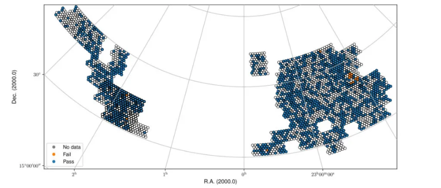
Fig. 23 Fall sky view of the released QU cubes, color-coded by whether they pass validation or not.
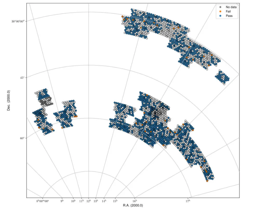
Fig. 24 Spring sky view of the released Stokes V mfs images, color-coded by whether they pass validation or not.
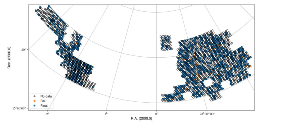
Fig. 25 Fall sky view of the released Stokes V mfs images, color-coded by whether they pass validation or not.
Released line data products
The released line data products include four dirty cubes and their associated dirty beam cubes. The three lowest frequency cubes (spectrally averaged by 3 channels) are validated independently, while the highest frequency, non-averaged cube (cube3) is not directly validated but generally follows the quality of the closest cube in frequency (cube2). The details of the validation are in “Validation of processed data products: HI”.
Table of all released beams with the line validation status (“G”ood, “O”kay, “B”ad, or “N”o cube) for cubes 0-2 (cube?_qual) plus the metrics used for the line validation (described in HI validation) can be exported using the VO infrastructure, more details are provided in section “User Interfaces”.
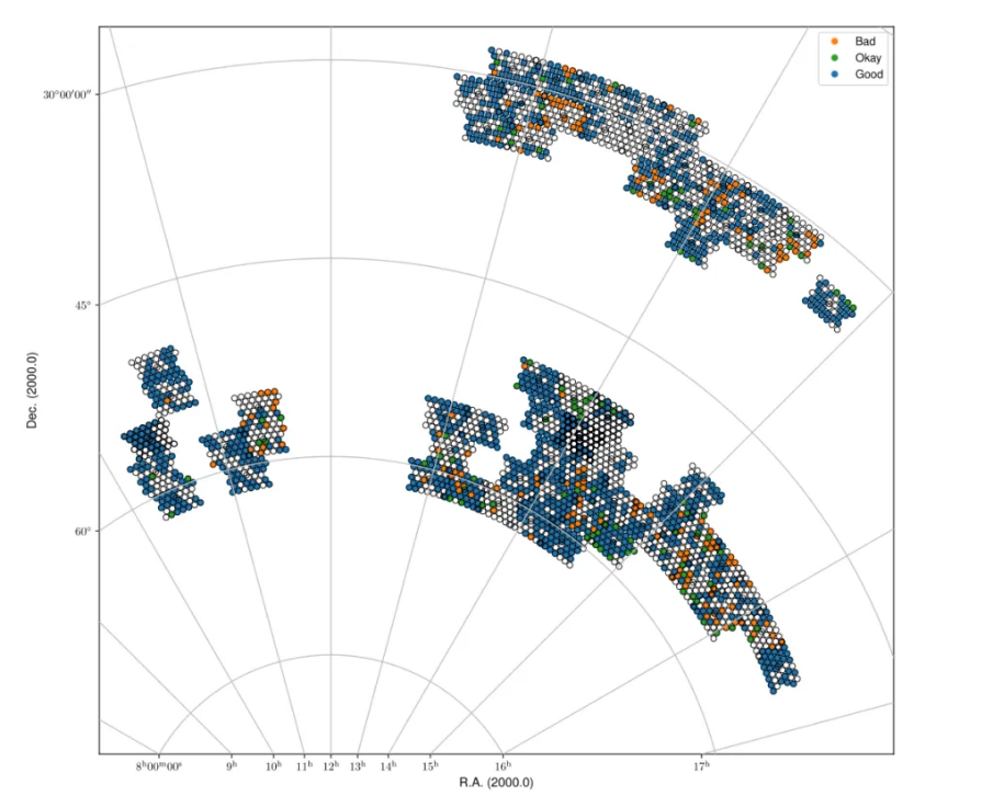
Fig. 26 Spring sky view of the released data for cube2, color-coded by status (Good, Okay, Bad).
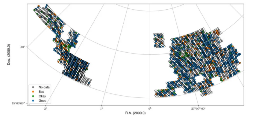
Fig. 27 Fall sky view of the released data for cube2, color-coded by status (Good, Okay, Bad).
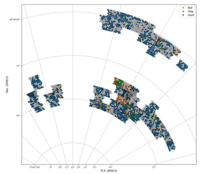
Fig. 28 Spring sky view of the released data for cube1, color-coded by status (Good, Okay, Bad).
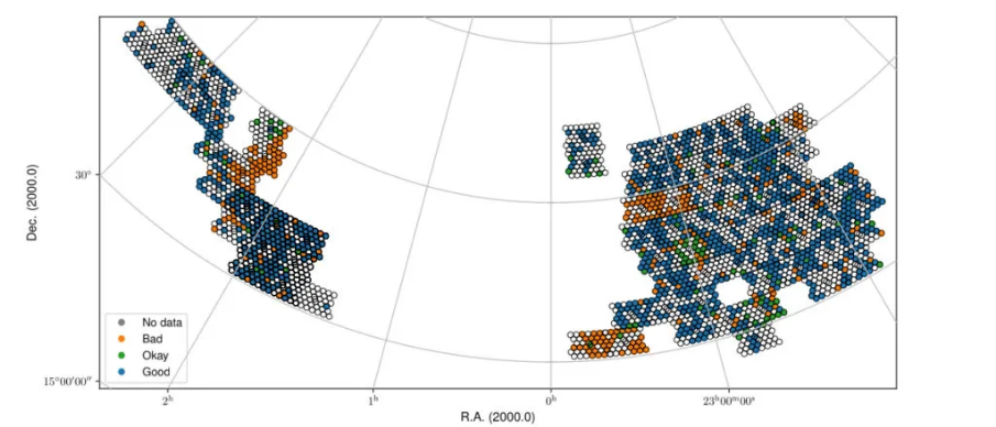
Fig. 29 Fall sky view of the released data for cube1, color-coded by status (Good, Okay, Bad).
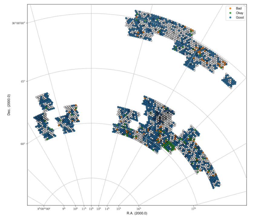
Fig. 30 Spring sky view of the released data for cube0, color-coded by status (Good, Okay, Bad).
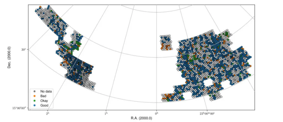
Fig. 31 Fall sky view of the released data for cube0, color-coded by status (Good, Okay, Bad).
Data Products
Available data products
Raw data Products
Raw observational data
The raw observational data is recorded in measurement-set (MS) format. A survey field observation consists of forty beams covering the field; with all dishes the size of this dataset is 4.6 TB. A set of calibration scans consists of 40 separate observations taken in succession. For each calibrator scan only one beam contains the calibrator. All other beams not containing the calibrator are discarded. These observations vary in between 3–5 minutes and the total datasize for a complete calibrator scan (all forty beams) is 64-106 GB. The calibrator observations are taken at a higher time resolution than the survey fields (10 vs. 30 seconds) to allow better RFI excision due to their shorter integration time. The raw data are stored in long-term storage at SurfSARA to enable future reprocessing with improvements to the Apercal pipeline.
Inspection plots
Upon ingest to ALTA, inspection plots showing various views of data quality are created. The majority of these plots show the behavior per compound beam, with different slices of the data to highlight different aspects of quality. Example inspection plots can be found here. These plots are:
- Amplitude(all): Amplitude across all beams, averaged over all parameters
- Amplitude f(time): Amplitude across all beams, concentric circles as a function of time inwards (start * to end)
- Amplitude f(antenna): Amplitude across all beams, concentric circles as a function of antenna inwards (RT2 to RTD)
- Amplitude f(baseline): Amplitude across all beams, concentric circles as a function of baseline inwards (in MS order)
- Phase (all): Phase across all beams, averaged over all parameters
- Phase f(time): Phase across all beams, concentric circles as a function of time inwards (start to end)
- Phase f(antenna): Phase across all beams, concentric circles as a function of antenna inwards (RT2 to RTD)
- Phase f(baseline): Phase across all beams, concentric circles as a function of baseline inwards (in MS order)
- Amplitude vs time: Baseline plot of amplitude as function of time, coloured by MS order of baselines
- Amplitude vs channel: Baseline plot of amplitude as function of channel, coloured by MS order of baselines
- Phase vs time: Baseline plot of phase as function of time, coloured by MS order of baselines
- Phase vs channel: Baseline plot of phase as function of channel, coloured by MS order of baselines
- Waterfall: scaled amplitude : Waterfall plot of amplitude as a function of channel (x-axis) and time (y-axis),with fixed scaling
- Waterfall: unscaled amplitude: Waterfall plot of amplitude as a function of channel (x-axis) and time (y-axis), no scaling
- Waterfall: scaled phase: Waterfall plot of phase as a function of channel (x-axis) and time (y-axis), fixed scale
- Waterfall: unscaled phase: Waterfall plot of phase as a function of channel (x-axis) and time (y-axis), no scaling
In addition, there are plots for a single beam, either the central compound beam for a target observation or the compound beam containing a calibrator for calibrator observations showing a full view of the data. These plots are:
- Beams XX: Waterfall plots of phase (upper right) and amplitude (lower left) for the XX polarization as a function of frequency (x-axis) and time (y-axis) for each baseline pair given by the antenna names (middle diagonal)
- Beams YY: Waterfall plots of phase (upper right) and amplitude (lower left) for the YY polarization as a function of frequency (x-axis) and time (y-axis) for each baseline pair given by the antenna names (middle diagonal)
Processed data products
The Apercal pipeline (see “Apercal overview and structure”) calibrates the data and produces final images and cubes per compound beam. All data products described below are for an individual compound beam, of which there are forty per observation. These data products are not primary-beam corrected; primary-beam images are provided separately (see the “Primary Beam Response” section, specifically “Released primary beam images”, and “User Interfaces”); these may be used for mosaicking or for correction of individual images.
Processed data products are ingested back into ALTA on a per-beam basis, and in “Released processed data products” we motivate the choice to release data on a per-beam basis. Note that the release of a beam releases all processed data associated with that beam.
An important note is that currently only the upper 150 MHz of the band is processed; thus the processed data products are produced over the range 1280-1430 MHz. Moreover, the first 12.5 MHz of data are flagged due to persistent RFI, therefore the resulting central frequency is 1361.25 MHz. The nominal bandwidth is then 137.5 MHz, but effectively it could be smaller due to additional RFI flagging. The (currently archived) data products are described below:
- Calibration tablesThe crosscal module portion of Apercal produces calibration tables that can be applied to the original data to reproduce the cross calibration. These tables are in standard CASA/MS format and a summary of all the calibration tables is provided in Table 5 , where 3CFFF refers to a flux/bandpass calibrator (namely, 3C147 or 3C196; occasionally 3C295) and 3CPPP to a polarization calibrator (namely, 3C286 or 3C138).Calibration tables and naming scheme.
-
Global delays 3CFFF.K Bandpass solutions 3CFFF.Bscan Intermediary, initial phase solutions 3CFFF.G0ph Final complex gain solutions 3CFFF.G1ap Crosshand delay 3CPPP.Kcross Leakage terms 3CFFF.Df XY phase offset 3CPPP.Xf - Full time, Stokes and spectral-resolution calibrated visibility dataAfter the completion of the self-calibration, the final selfcal solutions are applied to the full spectral resolution uv data, and this uv dataset is written out as a UVFITS file as an intermediate data product. Currently, the final calibrated uv-data are stored at full time and spectral resolution for all polarizations; this may change with future updates to the processing pipeline.
- Continuum imagesA multi-frequency Stokes I image is created over the full processed frequency range (currently 150 MHz; effectively less due to RFI occupancy) and saved as a FITS file for each beam. These images are 3.4°×3.4°(3073×3073 pixels, with 4′′/pixel). This samples well outside the primary beam response but is necessary to account for cases where a strong source is in a side-lobe and needs to be included in the self-calibration model and cleaning. Sources above 5-σ should be identified and cleaned to the 1-σ level.
- Polarization images and cubes A multi-frequency Stokes V image over the full bandwidth is produced. This image matches the continuum image in spatial extent: 3.4°×3.4°(3073×3073 pixels, with 4′′/pixel). In order to prevent bandwidth depolarization and enable rotation measure synthesis studies, Stokes Q and U cubes with a frequency resolution of 6.25 MHz are produced. The cubes have a smaller spatial extent of 2.7°×2.7°(2049×2049 pixels, with 4′′/pixel).
- Line and dirty beam cubes Four line cubes over a set of different frequency ranges are produced. Table 6 summarizes the covered frequency ranges and provides the corresponding redshift range for HI. The lowest redshift cube is produced at full spectral resolution while other cubes are produced with a 3-channel averaging. These cubes have a spatial extent of 1.1°×1.1°(661×661 pixels, with 6′′/pixel). As the Apercal pipeline does not provide source finding or cleaning of the line cubes, corresponding dirty beam cubes, with twice the spatial coverage, are also archived to allow offline cleaning of source emission. For cutting-down in archiving resources, taking advantage of the point symmetric structure, the dirty beam cubes have been reduced by a factor of two by cutting the beams in half. Informations how to recover to the full beam can be found here [https://github.com/apertif/trim_apertif_beam_cube]. Frequency/velocity coverage and resolution for all line cubes. Velocities use the optical definition and velocity resolutions are for the center frequency/velocity of each cube.
-
Cube0 1292.5 – 1337.1 18110 – 28226 0.062 – 0.099 36.6 8.3 Cube1 1333.1 – 1377.7 9155 – 19005 0.031 – 0.065 36.6 8.1 Cube2 1373.8 – 1418.4 424 – 10005 0.001 – 0.034 36.6 7.9 Cube3 1414.5 – 1429.3 -1873 – 1250 0 – 0.004 12.2 2.6
A summary of all the archived data products and their sizes (per beam and for a complete observation) are provided in Table 7 :
Summary of archived data products, including their format and sizes. For visibility data, the dimensions are for polarization and frequency. For images and cubes, the dimensions are for spatial sizes and frequency (when appropriate). The calibrator visibility sizes are after pruning to keep only the Apertif beam that contains the calibrator, and the range of sizes reflects the different calibrator scan lengths.
| Survey field raw visibility data | MS | 4 x 24576 | 117 GB | 4.7 TB |
| Calibrator raw visibility data | MS | 4 x 24576 | 1.6-2.6 GB | 64-104 GB |
| Calibration tables | MS table | – | 660 MB | 26.3GB |
| Self-calibrated visibility data | uvfits | 4 x 12288 | 58 GB | 2.3TB |
| Multi-frequency synthesis beam images | fits | 3073 x 3073 | 37 MB | 1.5 GB |
| Stokes Q and U cubes | fits | 2049 x 2049 x 24 | 1.5 GB | 62 GB |
| Stokes V multi-frequency synthesis image | fits | 3073 x 3073 | 37 MB | 1.5 GB |
| Continuum-subtracted dirty line cubes | fits | 661 x 661 x 1218 | 8 | 320 GB |
| Restoring beam cubes | fits | 1321 x 1321 x 1218 | 320 | 1.28 TB |
Validation of processed data products
Continuum
Image validation
The continuum images were individually validated for every beam. In order to do this, a set of metrics was defined which inform on different aspects of image quality. The starting point of the validation are the residual images obtained after cleaning the continuum images. The validation aims at checking to what extent these images only contain Gaussian noise. The premise being that any significant deviation from this indicates issues with the calibration and/or the reduction of the data.
The following parameters were derived for each residual image.
- σ_in: Noise in inner half degree of the image, determined in a robust way from the residual image using the median of the absolute values.
- σ_out Noise at the edge of the residual image, more than a degree from the centre determined in a robust way from the residual image using the median of the absolute values. This value is taken as a reasonable measure of the expected noise.
- R=σ_in/σ_out: A measure of the strength of artifacts left in the centre of the residual image.
- Ex-2: Area, in units of beam area, with values below 2 σ_out in the inner 0.5 degree of the residual image, in excess of what expected from a purely Gaussian distribution. For perfect noise Ex-2 = 0.
- MaxNeg: the level, in units of σ_out, at which the area covered by pixels with values below this level is 10 beams. The expected value is -3.2. More negative values indicate significant negative calibration residuals.
Note that we did not use the equivalents of the parameters Ex-2 and MaxNeg based on positive deviations from Gaussianity (Ex+2 and MaxPos). This is because many residual images have weak, positive residuals due to insufficient cleaning which would then dominate the validation.
Visual examination of a large set of images was undertaken to define the numerical criteria that would catch significant image artifacts, as used above. The main types of image artifacts due to errors in the selfcalibration as well as strong direction-dependent errors for which the calibration pipeline did not attempt to correct. The criteria were set so that the large majority of images which were visually assessed as good would pass while only a small fraction of images that were visually assessed as bad would be classified as good.
The final criteria used to reject images are: * R > 1.225. This criterion catches stripes due to errors in the amplitude calibration. * R > 1.15, MaxNeg < -4.5 and Ex-2>400. This criterion catches general image artifacts and deviations from Gaussianity in the residual image.
Two additional criteria were set based on survey specifications: * σ_in or σ_out > 60 microJy/beam. In this case the noise of the image does not meet the minimum requirement to be considered survey quality and valid. * The minor axis of the restoring beam is > 15 arcsec. This occurs when both dishes RTC and RTD are missing from an observation. In this case, the required angular resolution of the survey is not met.
Flux scale & astrometry
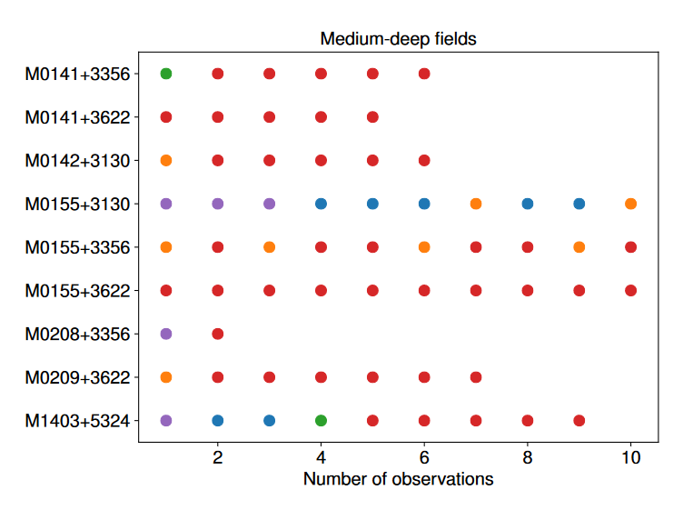
For checking the consistency of the flux scale two beams of an observation of a field in the Perseus-Pisces region centered on RA(J2000) = 01h55m and Dec(J2000) = 33d56’ which was observed ten times between September 2019 and January 2020 were examined. The automatic source finder PyBDSF (also used in the Apercal pipeline) was used to find and determine source fluxes, positions and sizes and compared these from observation to observation. We restricted the comparison to sources that are less than 35” in size and have fluxes above 3 mJy (100 times the typical rms noise) and agree in position to within 3 arcsecs to ensure that the sources used for comparison are indeed identical and have been included in the clean masks.
The overall consistency is very good with a mean of 1.014 and an rms of 4% . If one excludes the two most discrepant observations (ObsID 191207035 and 191227014) the rms decreases to 2%. Table 8 provides the flux ratio of 10 observations relative to the last observation made on 06.01.2020 (ObsID 200106010)
The flux ratio of 10 observations relative to the last observation made on 06.01.2020 (ObsID 200106010)
| 190919049 | 0.9982 |
| 191207035 | 0.9311 |
| 191223022 | 1.0041 |
| 191225015 | 1.0116 |
| 191227014 | 1.1069 |
| 191229014 | 1.0185 |
| 191231013 | 1.0062 |
| 200102012 | 1.0446 |
| 200104011 | 1.0222 |
| 200106010 | 1.0000 |
An example of two observations (ObsID 200106010 and 190909049, observed at 06.01.2020 and 09.09.2019 respectively) compared to one another is shown in Fig. 32. Plotted is the relative difference in flux versus the flux in the 06.01.2020 observation.
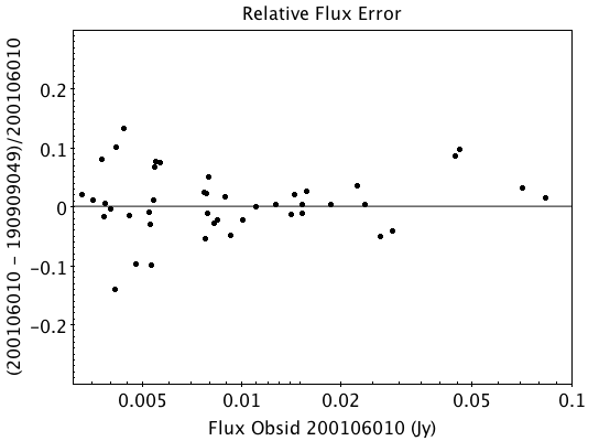 Fig. 32 Relative flux difference between the sources in a mosaic of ObsID 200106010 and a mosaic of ObsID 190909049 as a function of their flux measured in ObsID 200106010.
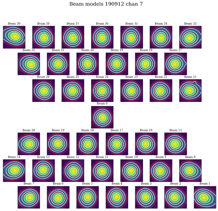
To assess the agreement with the NVSS we made mosaics of the full field of view (40 beams) of all observations using the measured shapes of the 40 beams. The reason for using mosaics rather than individual beams was to have a large enough number of sources for the comparison as in an individual beam there usually are only of order a dozen that are bright enough. The mosaicing routine takes into account shapes of the beams made with the phased array feeds as determined from drift scans across Cygnus A (see the section on Primary beam response: Drift scan method) and corrects for the presence of correlated noise in adjacent beams. The mosaics were made with a resolution of 28” x 28”. We ran PyBDSF on the mosaics to produce a source catalog and compared sources in this catalogue with the sources in the NVSS source catalog extracted from VizieR. For the comparison we restricted ourselves to sources that agree in position to within 4”, are less than 28.5” in size and stronger than 3 mJy in the Apertif mosaic.
Table 9 captures the comparison of the individual mosaics with the NVSS. For each ObsID the median flux ratio NVSS / Apertif is given. On average the Apertif flux scale is 3% above the NVSS flux scale for these mosaics with an rms of 4%. If the two most discrepant ObsIDs are omitted (191207035 and 191227014) the rms reduces to 2%. Fig. 33 illustrates the agreement between the Apertif and NVSS flux scale for ObsID 200102012. Since the observing frequency of the mosaic is 1360 MHz as opposed to the 1400 MHz of NVSS ~2% of the flux difference can be accounted for by spectral index effects (assuming an average spectral index of -0.7) which were not taken into account.
Median flux ratio NVSS/Apertif for each ObsID
| 190919049 | 0.943 |
| 191207035 | 0.894 |
| 191223022 | 0.962 |
| 191225015 | 0.969 |
| 191227014 | 1.083 |
| 191229014 | 0.980 |
| 191231013 | 0.974 |
| 200102012 | 1.004 |
| 200104011 | 0.976 |
| 200106010 | 0.964 |
A flux scale comparison using the beam shapes determined from a direct comparison of the DR1 observations with NVSS using a Gaussian process regression technique provides a better picture as all DR1 data are used rather than just one field.
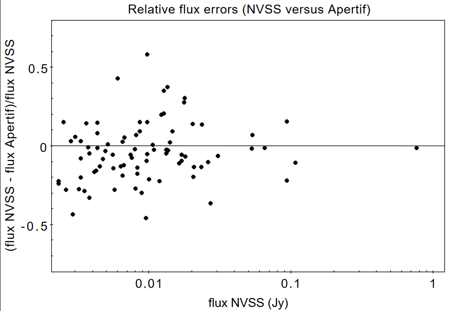 Fig. 33 Relative flux difference of sources in the NVSS catalogue and sources measured in an aperitif mosaic of ObsID 200102012 as a function of the flux of the sources in the NVSS catalogue
This is described in “Characterization of the primary beams” and yields a current estimate of the flux scale of Apertif as compared to NVSS. From this comparison the Apertif fluxes are on average 9% higher than those of NVSS, accounting for a nominal spectral index of the sources of -0.7.
Since we had to match sources in Apertif and NVSS for the source comparison we also obtained information on the agreement between the Apertif and NVSS astrometry. Fig. 34 shows the positional differences for sources in the mosaic of ObsID 200102012 and the NVSS catalogue. The agreement is very good with mean offsets of 0.05 +/- 0.2 arcsec in RA and -0.05 +/- 0.2 arcsec in Dec.
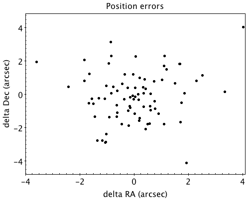
Fig. 34 Position difference between the sources in the NVSS catalogue and the sources detected in the mosaic of ObsID 200102012.
Polarization
Validation of polarisation cubes/images
Two types of polarisation products are generated by the pipeline. The first one being cubes of Stokes Q and U of 24 images each covering a bandwidth of 150 MHz resulting in a frequency resolution of 6.25 MHz. The second products are Stokes V images generated from the whole combined bandwidth of 150 MHz.
Due to the different characteristics of these products two different sets of metrics were used to validate their quality. These metrics are very similar to the ones used for the continuum validation, but needed to be adjusted due to the following reasons:
# Due to the physical nature of Stokes Q, U and V emission in the cubes can be a positive or negative quantity while it can only be positive in Stokes I. # Image artefacts are mostly influenced by the instrumental leakage characteristics of the primary beam in combination with direction dependent effects. This means that the strongest artefacts often appear for sources far away from the beam centres where the instrumental leakage is higher. # For Stokes Q and U even faint artefacts in individual images can stack up if those are present over the whole cube at a similar position once the RM-Synthesis technique is applied in later stages of the analysis. This is also possible vice versa where strong artefacts in an individual image can be averaged out in this process and lead to a good image quality after RM-Synthesis processing. # Stokes V represents the circular polarisation. Astronomically circularly polarised sources are extremely rare and most often show percentage polarisation of below 1%, so that Stokes V images should normally be regarded as empty.
In the following we describe the sets of metrics and the determined values for the quality assurance of the polarisation cubes/images. All values and the validation information for released beams is available in the table of the survey data release for polarisation observations.
Stokes V validation
The following parameters were derived for each Stokes V image:
- σ_in: rms in the inner part of the image, which is defined as a radius of <30′ around the central coordinate of a beam [microJy/beam]
- σ_out: rms in the outer part of the image, which is defined as a radius of >60′ around the central coordinate of a beam [microJy/beam]
- FT_max: Absolute of the Fourier Transformation of the image. This value gives a good measure of repeating structures in the image such as amplitude artefacts which manifest as stripes.
- peak_inner: The maximum of the absolute values of the inner part of the image as defined in σin (see above) [microJy/beam]
- b_min: The diameter of the FWHM minor axis of the synthesised beam [arcseconds]
A Stokes V image fails validation if one of the following criteria is met:
# σ_in and/or σ_out > 60 microJy/beam. This is the same value as for the continuum validation. # b_min > 15’’. This criterium filters any images for observations where failing or missing dishes are raising the FWHM of the synthesised beam above a value which is not acceptable for the survey. # FT_max > 25. This value was empirically determined and filters any image, which is suffering from leftover RFI or strong amplitude errors. # peak_inner > 4mJy. Images with values above this limit are most likely strongly affected by instrumental leakage and in most cases also show strong artefacts.
The first two criteria match that of the continuum validation and are based on survey specification. The second two criteria were empirically determined to filter images with strong polarization artefacts. Stokes Q&U validation
Stokes Q/U cubes are validated depending on how many planes in a cube fail the following two criteria:
# The synthesised beam’s minor axis of an image is larger than 17.5’’. We are using a slightly larger value here compared to the continuum or Stokes V validation due to the fact that the beam becomes larger for images at lower frequencies. # The rms noise in an image is larger than 300 microJy/beam. This corresponds to the same noise level as for the continuum and Stokes V images assuming a homogeneous noise distribution along the frequency axis. Stacking 24 images would reduce the noise by a factor of ~5.
Beams where more than one third of the images (>8) in Stokes Q or U are failing either of the above mentioned criterium do not pass the validation.
The table of released polarisation beams includes the following columns that describe the Stokes Q/U data quality:
- Qbeam_frac: Fraction of Q image planes failing criterium 1. [0.0-1.0]
- Ubeam_frac: Fraction of U image planes failing criterium 1. [0.0-1.0]
- Qnoise_frac: Fraction of Q image planes failing criterium 2. [0.0-1.0]
- Unoise_frac: Fraction of U image planes failing criterium 2. [0.0-1.0]
HI
Cube Validation
The quality of the HI line data was validated in multiple steps. We concentrate the analysis on cubes 0, 1, and 2 (see Table 6 in the “Available data products” document for the frequency ranges of the cubes), as the quality of cube 3 always followed that of cube 2 due to both of them being in adjacent low-RFI frequency ranges.
As a first step all cubes 0, 1, and 2 where the average rms noise was larger than 3 mJy/beam were rejected. Inspection of the cubes showed that such large noise values always indicates the presence of major artefacts in the cube.
We then constructed noise histograms for cubes 0, 1 and 2 of each observation and beam combination. We made no attempt to flag any sources prior to determining the noise histogram. The HI cubes are mostly empty (i.e. consist of noise pixels) and real sources have no discernible effect on the histogram. The only exception is that all cubes 0 were blanked below 1310 MHz to remove the impact of residual RFI at these frequencies.
We also extracted representative channels as well as position-velocity slices from each cube. The cubes of 14 observations (~550 cubes) were inspected by eye for the presence of artefacts and to gauge the impact and effect of data artefacts on the noise histograms.
Artefacts generally fell in two categories: due to imperfect continuum subtraction and due to imperfect sub-bands, which we discuss in turn.
- Continuum subtraction artefacts
Continuum subtraction artefacts (and with it the presence of residual grating rings) add broad wings with extreme positive and negative values to the noise histogram. Trial and error showed that these wings could be robustly detected by quantifying the fraction fex of the total number of pixels with an absolute value flux value >6.75σ where σ is the standard rms noise in the cube. While adding wings of extreme value pixels to the histogram, these artefacts in general do not affect the Gaussian shape of the central part of the histogram (i.e., at low σ values).
- Sub-band artefacts
The presence of sub-bands with lower quality (i.e., a higher noise) manifests itself not by wings of extreme pixels but by a systematic change in the shape of the histogram through the addition of “shoulders” to the histogram (lower kurtosis). Trial and error showed that the presence of these features were best detected by comparing the rms width of the histogram with that at the level of 0.8 percent of the maximum of the histogram. We define the parameter p0.8 or the ratio of this 0.8 percent width and the rms.
We compared our “good”, “bad” or “OK” rankings as determined by eye for the 14 observations with the corresponding fex and p0.8 values. This is illustrated in Fig. 35 where we show the distribution of all cubes 2 in the fex-p0.8 plane with the cubes which we inspected by eye color coded to indicate their quality ranking.
“Good” cubes, i.e., those with no or very minor artefacts, were concentrated in a small part of parameter space obeying the following criteria:
- rms < 3 mJy/beam
- log(fex) < -5.30
- p0.8 < 0.25 fex + 5.875
A second criterion defines cubes of OK quality, containing some minor artefacts. This consists of cubes meeting the following conditions:
- rms < 3 mJy/beam
- -5.30 < log(fex) < -4.52
- p0.8 < 0.5 fex + 7.2
The upper limit of -4.52 of the second condition is not a hard limit and a slightly different value could also have been chosen. We found however that the values used here give a good compromise in minimizing the number of false qualifications of “OK” cubes
Cubes not obeying any of these two sets of criteria were considered “bad”. Using these conditions we defined for all cubes 0, 1 and 2 a subset of good and OK cubes. Cube 3 in all cases follows the quality designation of cube 2.
Fig. 36 shows the noise histograms and a representative channel map and position velocity slice for each of the three quality categories.
Whether a cube is part of the data release is determined by the quality criteria of the corresponding continuum image. This is described in more detail in the document “Released processed data products”. The quality of each cube and the metrics used to determine that quality are included in the VO table describing the released HI observations (see “User Interfaces”).
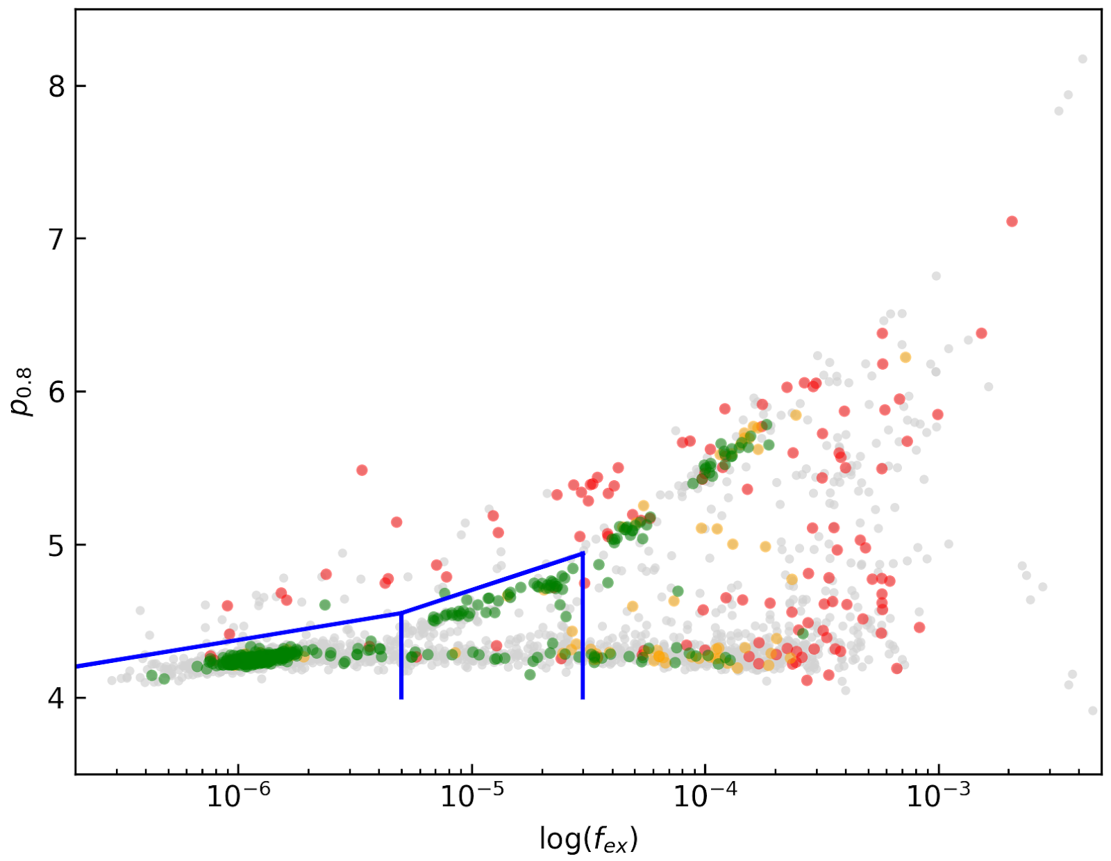 Fig. 35 Distribution of cubes 2 of all beams in the fex-p0.8 plane (grey points). Overplotted are quality assessments of the beams of 14 observations. Good cubes are indicated by green points, OK by orange points and bad cubes by red points. The blue lines indicate the regions where cubes are considered good (left region) or OK (right region).
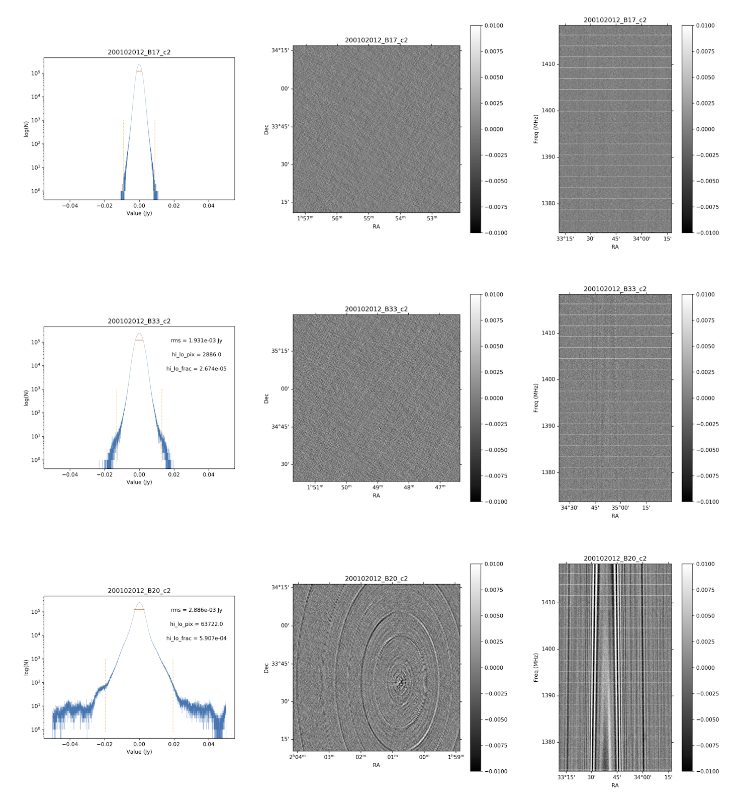 Fig. 36 Examples of the three quality classes used for the HI quality assessment. The top row shows an example of a “good” observation (Obsid 200202012, beam 17, cube 2), the middle one an “OK” observation (Obsid 200202012, beam 33, cube 2) and the bottom one a “bad” observation (Obsid 200202012, beam 20, cube 2). The columns show, from left to right, the noise histogram, an extract of the central velocity channel, and a position-velocity diagram through the center of the cube. In the plots in the left column the short horizontal line at the top indicates the rms. The two dotted vertical lines indicate the ±6.75 x rms values. The “good” observation in the top row shows hardly any artefacts and a Gaussian noise histogram. The “OK” observation in the middle row shows a minor continuum subtraction artefact (which in turn causes somewhat extended wings to the noise histogram). The “bad” observation in the bottom row shows major continuum subtraction artefacts, resulting in a very non-Gaussian histogram.
External comparison
In order to further validate the line cubes, we performed preliminary source finding and cleaning of a subset of cubes using SoFiA-2 (Source Finding Application; Serra et al. 2015, https://github.com/SoFiA-Admin/SoFiA-2). Full details of this procedure are supplied in Hess et al. (in prep).
Comparison to ALFALFA
We compared the properties of HI detections in Apertif with the properties of HI detections in the ALFALFA catalogue (Haynes et al. 2018). We created a source catalogue with SoFiA and cross matched the detected sources with the ALFALFA catalogue. In 21 fields that overlap in the footprint of both surveys, we found 479 matching sources. Out of these, 336 sources were found in data cubes with “good” quality, 39 in data cubes with “OK” quality and 104 were found in “bad” quality data cubes. The results of the comparison are shown in Fig. 37 and Fig. 38. The color coding of these figures reflects the quality of the data cube in which the sources were identified with blue for “good”, green for “OK” and orange for “bad”.
Overall the properties of the Apertif detections agree well with the ALFALFA detections. There are some sources that have smaller line widths (w20) than the ALFALFA sources. This is likely connected to the flagging of 3 channels out of every 64 because of the strong dropoff in response (See “Aliasing” in “System notes”). Cubes 0, 1, and 2 have every three channels averaged together. Combined with the flagging of three channels out of every 64, this means that every 22nd channel in these cubes has no signal, and there are channels with ⅓ nominal sensitivity (periodicity of 42 and 21 channels) and ⅔ nominal sensitivity (periodicity of 63 channels). These flagged or partially flagged channels can result in a source being spectrally separated into two different detections. This then also results in smaller line widths for these sources. Another reason for the smaller line widths in Apertif can be extended emission detected in ALFALFA that gets filtered out by the interferometry.
 Fig. 37 Comparing the properties of overlapping Apertif and ALFALFA sources. First panel: systemic velocity, second panel: W20 line width, third panel: integrated flux. The different colored markers represent sources detected in “good” (G), “OK” (O), and “bad” (B) quality HI data cubes.
 Fig. 38 Distribution of the difference in systemic velocity, W20 and integrated flux between Apertif and ALFALFA detections. The colors represent detections in “good” (G), “OK” (O), and “bad” (B) quality HI data cubes.
User Interfaces
The Apertif Data Release 1 (Apertif DR1) is hosted on the Apertif Long Term Archive and exposed to the community through the standard Virtual Observatory protocol. This section describes how the Apertif DR1 data products can be queried and accessed by using different applications.
Introduction
The science-ready data products as described in Available data products and Released processed data products are exposed through standard Virtual Observatory protocols to facilitate their access and exploration.
The Apertif DR1 data is hosted on the Apertif Long Term Archive (ALTA) system. We recommend astronomers to use the VO interfaces described below for data discovery. These interfaces will redirect to ALTA file servers for data access where appropriate.
In particular, the protocols offered are the Tabular Access Protocol (TAP), Simple Application Messaging Protocol (SAMP) and the Simple Image Access protocol (SIA). TAP and SAMP enables queries to explore the data in a tabular form using tools such as TOPCAT. TOPCAT is an interactive graphical viewer and editor for tabular data, it enables the interactive exploration of large tables performing several types of plotting, statistics, editing and visualization of tables. SIA enables the rapid display of images and cubes through all sky atlas tools such as ALADIN. ALADIN is an interactive sky atlas allowing the user to visualize digitized astronomical images/cubes and superimpose entries from astronomical catalogues or databases.
The data published in the VO can also be accessed using a web browser at https://vo.astron.nl. This web interface provides a page on which all the collections present in the registry are listed, including the published Apertif DR1 data sets (Fig. 39).
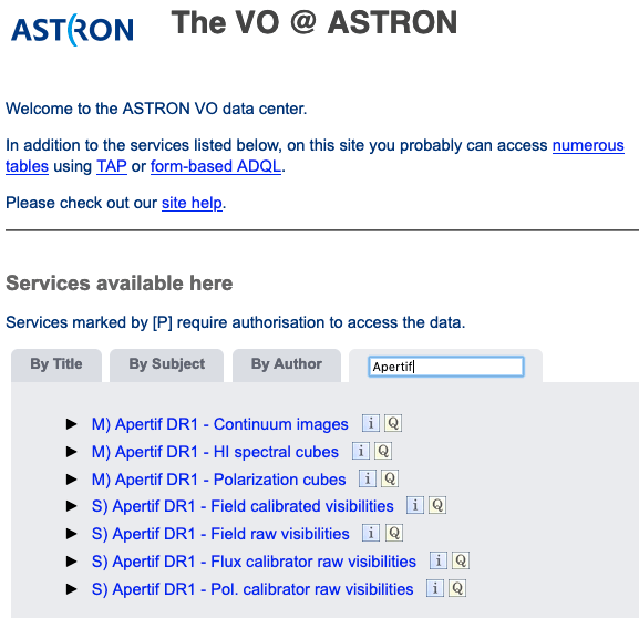 Fig. 39 ASTRON VO interface.
Selecting a data collection allows the user to perform a cone search through a webform (Fig. 40) for all data products of that given class overlapping a given pointing. The size of the continuum images as well as the cubes extend beyond the 10% primary beam level for cleaning the secondary lobes of bright offset sources. To ensure that the search is done in the area of maximum sensitivity the search is performed on a maxim radius of 0.75 degrees from the center (this represents the average value of where the sensitivity drops). This value can be modified using the Max distance from center. A different output with respect to the default can be customized using More output fields selection button.
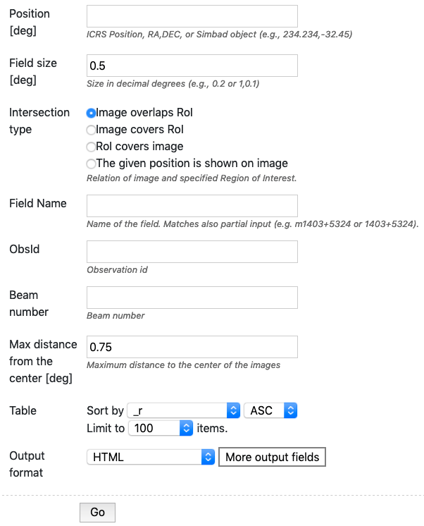
Fig. 40 Query search form for continuum images.
The result is a table in the requested output format in which every row corresponds to a data product (Fig. 41).
In each row there is a column, Product key, which is a link that allows the user to download the fits file of the image or the cube of interest.
The selected target and the position of the individual beams can be visualized using the Quick plot button at the top of the window of the results of the search query (Fig. 41).
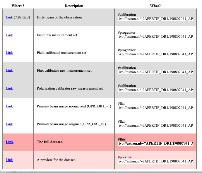
In the column Related products another link connects to a page containing a list of links to additional related data that can be useful to interpret or reanalyze that given product (e.g. primary beam images), for which a preview is provided (Fig. 42).
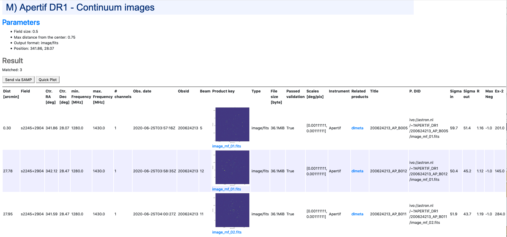
Fig. 41 Result of the search query.
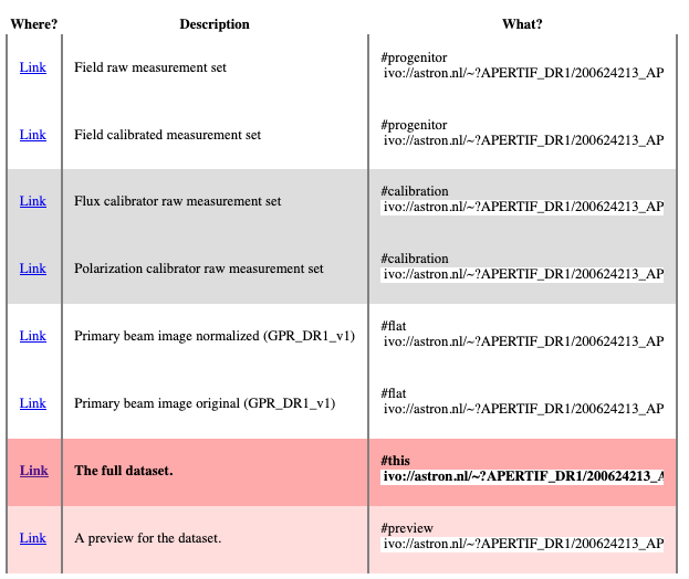
Fig. 42 Links of ancillary data products related to the target of interest.
The columns shown in Figure 3 are the most informative for the astronomers (e.g. position, observing frequency, observing date, quality assessment, format etc), please note that more columns are available but not displayed here. The complete set of columns can be visualized via topcat as described below or using More output fields selection button in the search query. Querying the released data is also possible using e.g. TOPCAT using TAP. Via the TAP protocol, it is possible to query the registry in a more flexible way using an enriched SQL syntax called ADQL. An example is given in Fig. 43 : click the link indicated with the red ellipse on the left panel Try ADQL and place your ADQL query on the query form.
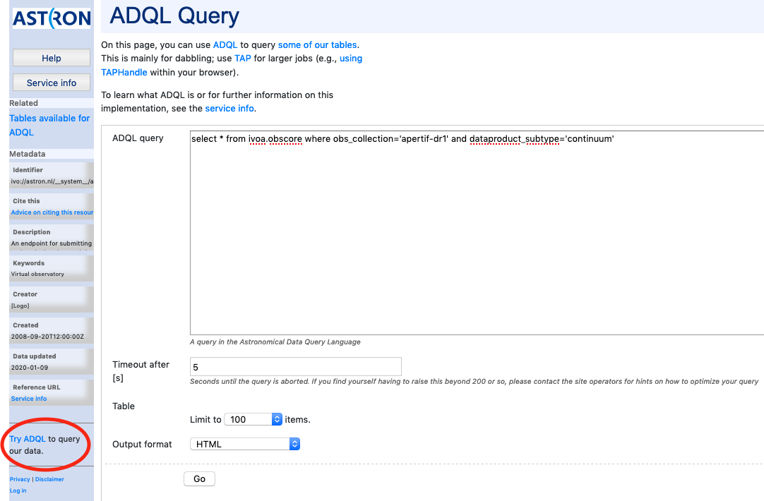
Fig. 43 ADQL query form.
The table names to use in the query form of Fig. 43, are summarized in Table 10. The URL for the query is then: https://vo.astron.nl/apertif_dr1/q/{Table name}/form (e.g. http://vo.astro.nl/apertif_dr1/q/apertif_dr1_continuum_images/form}.
It is possible to query all the available dataproducts at once by using the table ivoa.obscore and by appending to the ADQL statement “where obs_collection=” it is possible to limit the search to the apertif_dr1 only.
VO-Apertif DR1 Processed Data Products
Table names to be used in the ADQL query.
| Table name | obscore type | obscore subtype |
|---|---|---|
| apertif_dr1.continuum_images | image | continuum |
| apertif_dr1.pol_cubes | cube | polarization cube |
| apertif_dr1.spectral_cubes | cube | spectral cube |
| apertif_dr1.beam_cubes | cube | dirty beam |
Access via TOPCAT
The Apertif DR1 data collection tables can be accessed using TOPCAT, an interactive graphical viewer and editor for tabular data. The data can be sent from vo.astron.nl to TOPCAT using one of the two protocols: SAMP or TAP. The two subsections below provide a description on how to access the tabular data using either SAMP(link to Send via SAMP subsection) or TAP(link to VO Table Access Protocol (TAP) subsection).
Send via SAMP
With TOPCAT opened, and once you are satisfied with the output of the cone search in the Astron VO webform, click the grey button “Send via SAMP” as shown on the top of the output list of Figure 3. Authorize the connection and wait until the download is completed.
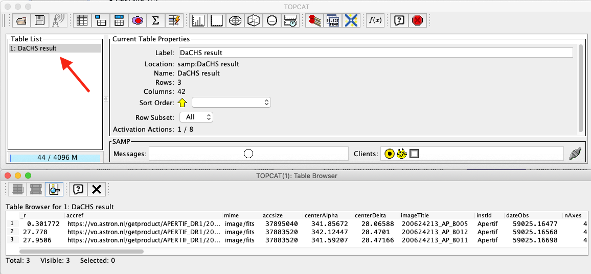
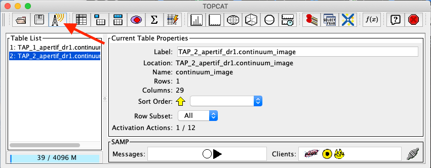
Once completed, the catalogue will be visible in the left panel of TOPCAT (Table List). Click on the new entry as shown by the arrow in Fig. 44. At this point the table browser will open showing the content of the DACHS results (PLACE HOLDER use DR1 in selection). From here any TOPCAT tool can be used for further inspection and analysis of the results. Alternatively the table can be saved in various formats and used locally with other programs (e.g. python scripts etc).
Fig. 44 TOPCAT table browser view of the Apertif DR1 data collection tables.
VO Table Acess Protocol (TAP)
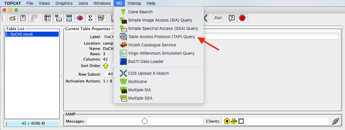
From the TOPCAT menu bar, select VO and in the drop down, select Table Access Protocol (TAP) as shown by the red arrow in Fig. 45.
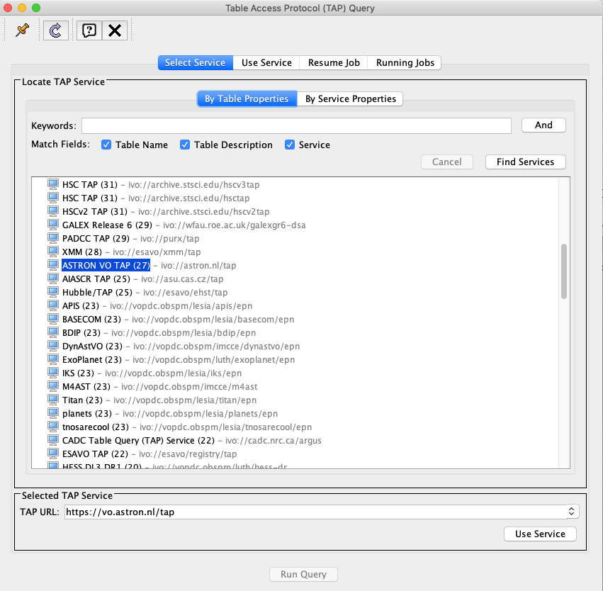
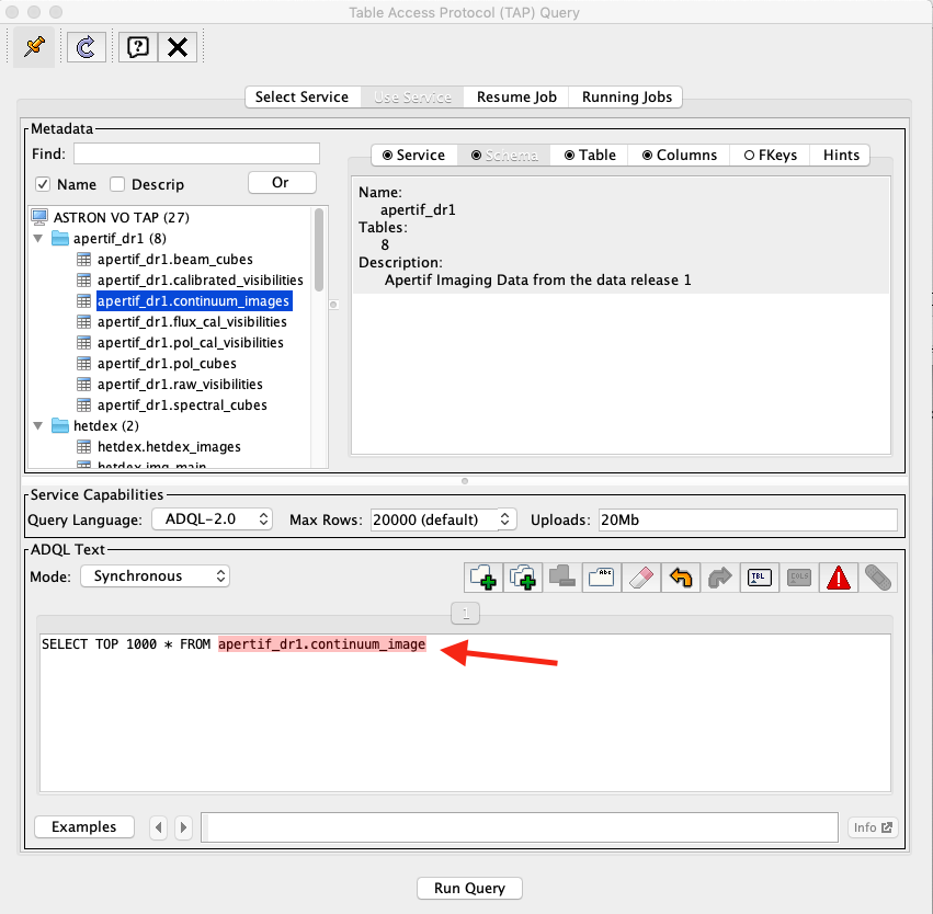
This will open the Table Access Query window where the ASTRON VO TAP server is listed. Select it and click on Use Service at the bottom of the window (Fig. 46). Another tab will open showing the Apertif DR1 data collection. Select one, e.g. continuum image, and enter a query command in the bottom panel, an example of which is indicated by the red arrow in Fig. 47. Submit the query using Run Query. This will show the resulting table in the Table list view shown before in Fig. 44. From here, any TOPCAT tool can again be used. As mentioned in the previous section, the query result in vo.astron.nl will display a subset of the columns of the Apertif DR1 table (e.g. position, observing frequency, observing date, quality assessment, format etc). The complete set of columns (e.g. pipeline version, wcs references etc) belonging to each data collection of the Apertif DR1 can be explored using the option described in this section.
The position of the targets can be visualized using the option skyplot in TOPCAT, once the search query has been sent via SAMP or TAP as described in this section.
Fig. 45 TOPCAT menu bar for VO services.
Fig. 46 TOPCAT TAP service query form.
Fig. 47 TOPCAT menu bar for VO services. Click for a bigger image.
Another useful way to inspect the Apertif DR1 data collection, but also other data collections exposed via the ASTRON-VO, is the ivoa-obscore table. The same selection as before can be used (Fig. 47) but instead of selecting Apertif_dr1 tables, the table ivoa.obscore is to be selected. In this way it is possible to glance over all the data collections exposed via the ASTRON-VO. This might be useful for instance to enable multi-wavelength science exploring LOTSS and Apertif DR1 data or, as mentioned in the case of the ADQL query, to visualize multiple data collections at once.
Having ALADIN open, and once you are satisfied with the resulting table, it can be sent to ALADIN following the instructions of Fig. 48.
Fig. 48 How to transfer the TOPCAT query results to ALADIN.
Access via ALADIN
Catalogues
The Apertif DR1 VO data collection can also be discovered directly via ALADIN either via simple image access protocol (SIAP) or tabular access protocol (TAP). The examples shown here require the desktop version of ALADIN.
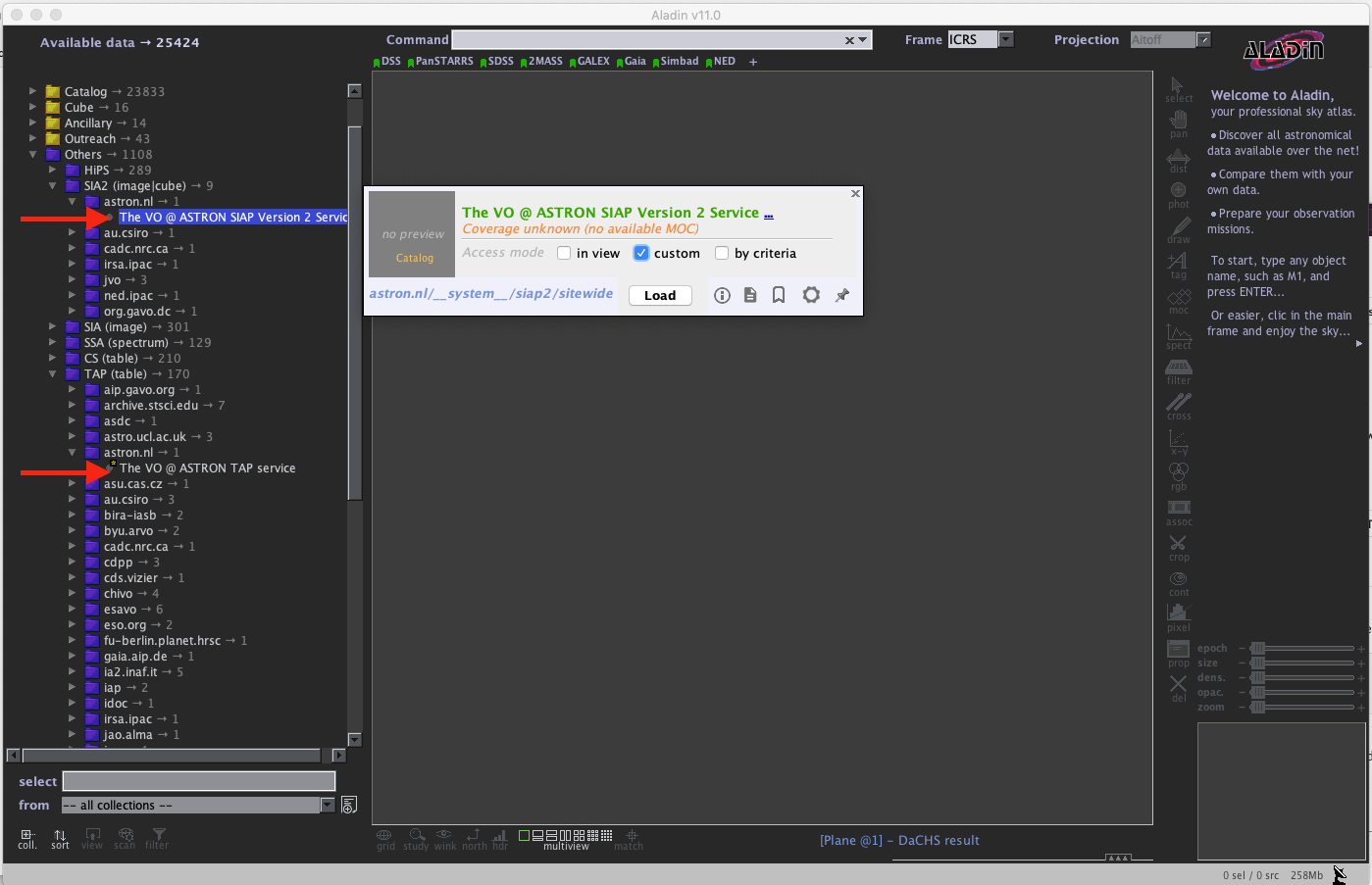
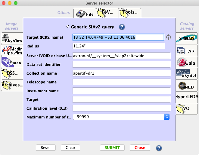
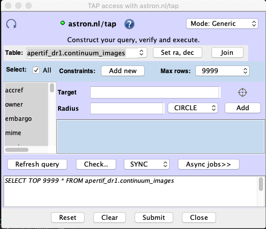
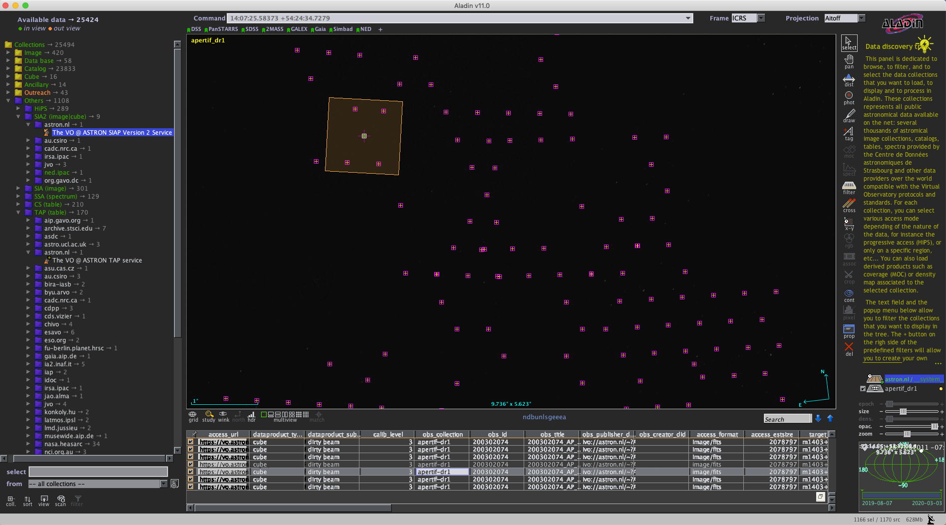
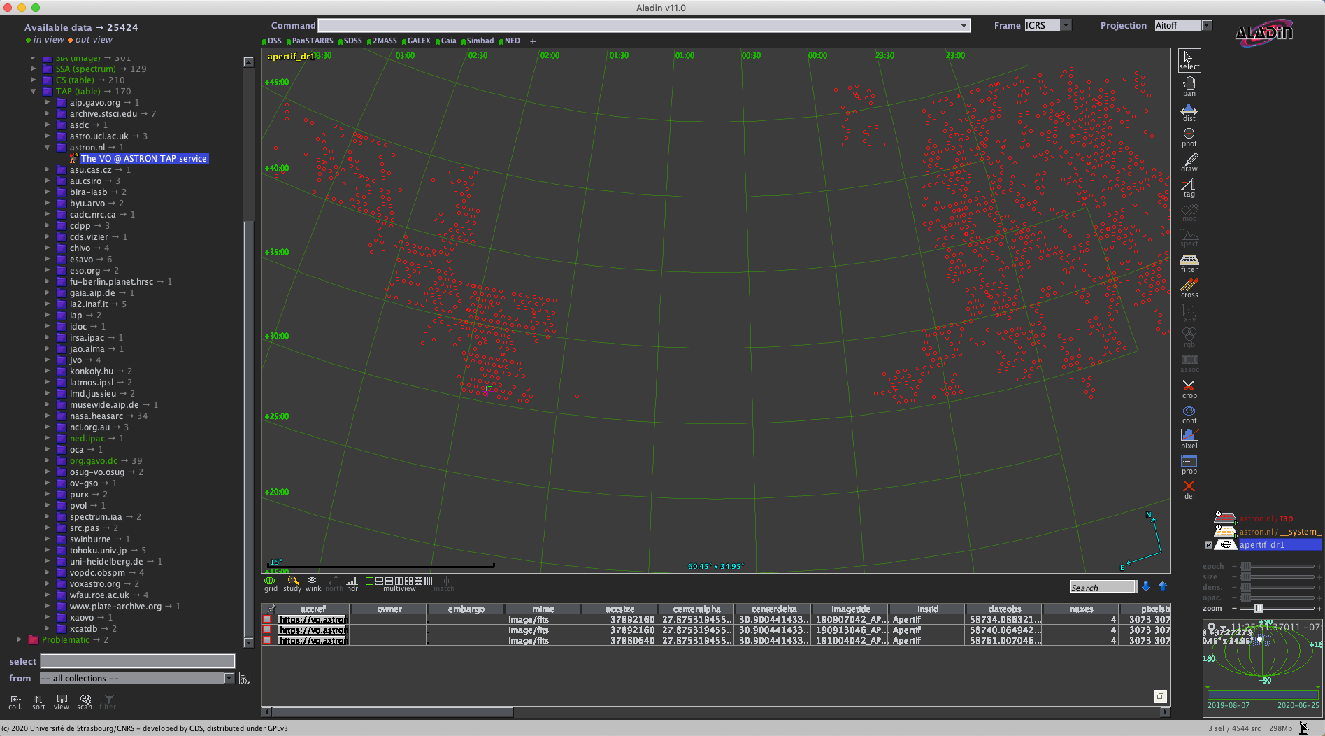
Open ALADIN and on the left panel for SIAP: select Others > SIA2 > astron.nl > The VO @ASTRON SIAP Version 2. Alternatively for TAP select Others > TAP > astron.nl > The VO @ASTRON TAP service (Fig. 49). A pop-up window will open. Click load, and enter a query using the Server selector (Fig. 50) or TAP access with astron.nl/tap (Fig. 51) to select the target of interest for SIAP and TAP respectively.
Fig. 49 ALADIN display panel.
Fig. 50 ALADIN server selector panel for SIAP.
Fig. 51 ALADIN TAP access panel.
After loading, the data collection catalogues can be plotted on the main panel by selecting them first on the right panel (e.g. highlighted in blue in Figures 14 and 15) and then by selecting the regions of interest on the bottom panel as shown in Figures 14 and 15. From here the usual functionality of ALADIN can be used.
Fig. 52 Example of data collection selection via SIAP in ALADIN.
Fig. 53 Example of data collection selection via TAP in ALADIN.
Images
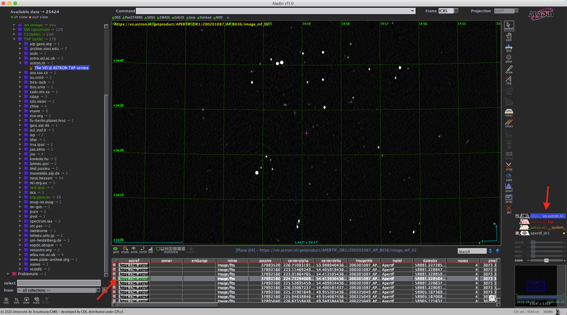
Downloading images or cubes in ALADIN is also possible (see Fig. 54). The user will need to click on the url-link in the column access_url of the bottom panel. Then, once the image is loaded, click on the right panel as shown in Fig. 54. From here the usual functionality of ALADIN can be used.
Fig. 54 Example of image selected from the Apertif DR1 displayed in ALADIN.
Access to raw and calibrated visibilities
Raw observations and calibrated visibilities can be discovered in the data collection as shown in Fig. 39, using the ASTRON-VO query form (Fig. 40) or via TAP using TOPCAT.
In addition, the query results via ASTRON VO for continuum images, polarization images/cubes, and HI spectral cubes provides a link to ancillary data (Fig. 42), including raw and calibrated visibilities.
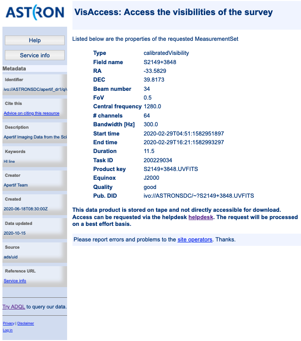
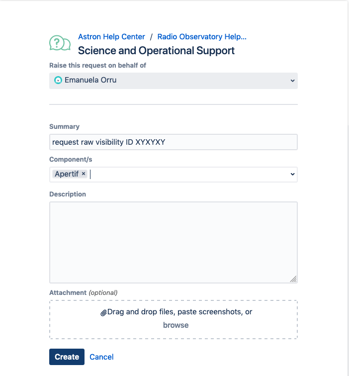
These data products are stored on tape and not directly accessible for download, but until further notice access can be requested via the helpdesk (Fig. 56). The request will be processed on a best effort basis. Within the same request also the calibration tables can be made available (see “Available data products”).
Fig. 55 Visibility data access page.
Fig. 56 Astron help center webpage.
Primary beam images
The continuum images, HI spectral cubes and V images and Q&U cubes are not primary beam corrected. Primary-beam images may be used for mosaicking or for correction of individual images. More information about the primary beam images for Apertif, including their derivation, can be found in the “Overview of primary beam shapes for Apertif”. Specifically, “Released primary beam images” describes the primary beam images initially made available as part of this data release. As for other ancillary data products, primary beam images can be found in the query results following the links in the column Related products (Fig. 57) for continuum images, HI spectral cubes or polarization cubes.
Fig. 57 Links to ancillary data.
Python access
The data collection and the table content can be accessed directly via python using the pyvo tool. Working directly in python the tables and the data products can be simply queried and outputs can be customized according to the user’s needs, without the involvement of TOPCAT or ALADIN.
An example of a TAP query and image download can be found in the python script below (it has been tested for python 3.7). The result of the query can also be plotted using python.
#To start you have to import the library pyvo (it is also possible to use astroquery if you want)
import pyvo

## To perform a TAP query you have to connect to the service first
tap_service = pyvo.dal.TAPService('https://vo.astron.nl/__system__/tap/run/tap')

# This works also for
form pyvo.registry.regtap import ivoid2service
vo_tap_service = ivoid2service('ivo://astron.nl/tap')[0]

# The TAPService object provides some introspection that allow you to check the various tables and their
# description for example to print the available tables you can execute
print('Tables present on http://vo.astron.nl')
for table in tap_service.tables:
 print(table.name)
print('-' * 10 + '\n' * 3)

# or get the column names
print('Available columns in apertif_dr1.continuum_images')
print(tap_service.tables['apertif_dr1.continuum_images'].columns)
print('-' * 10 + '\n' * 3)

## You can obviously perform tap queries accross the whole tap service as an example a cone search
print('Performing TAP query')
result = tap_service.search(
 "SELECT TOP 5 target, beam_number, accref, centeralpha, centerdelta, obsid, DISTANCE(" \
     "POINT('ICRS', centeralpha, centerdelta),"\
     "POINT('ICRS', 208.36, 52.36)) AS dist"\
 " FROM apertif_dr1.continuum_images"  \
 " WHERE 1=CONTAINS("
 "    POINT('ICRS', centeralpha, centerdelta),"\
 "    CIRCLE('ICRS', 208.36, 52.36, 0.08333333)) "\
 " ORDER BY dist ASC"
 )
print(result)

# The result can also be obtained as an astropy table
astropy_table = result.to_table()
print('-' * 10 + '\n' * 3)

## You can also download and plot the image
import astropy.io.fits as fits
from astropy.wcs import WCS
import matplotlib.pyplot as plt
import requests, os
import numpy as np

# DOWNLOAD only the first result
#
print('Downloading only the first result')
file_name = '{}_{}_{}.fits'.format(
 result[0]['obsid'].decode(),
 result[0]['target'].decode(),
 result[0]['beam_number'])
path = os.path.join(os.getcwd(), file_name)
http_result = requests.get(result[0]['accref'].decode())
print('Downloading file in', path)
with open(file_name, 'wb') as fout:
 for content in http_result.iter_content():
     fout.write(content)
hdu = fits.open(file_name)[0]
wcs = WCS(hdu.header)
# dropping unnecessary axes
wcs = wcs.dropaxis(2).dropaxis(2)
plt.subplot(projection=wcs)
plt.imshow(hdu.data[0, 0, :, :], vmax=0.0005)
plt.xlabel('RA')
plt.ylabel('DEC')
plt.show()
|
Export machine readable table
There are multiple ways to export a catalog of the various data products of the data release. On the vo.astron.nl pages, the results of a query can be exported to a csv file or fits table; running an empty query with a table limit of 5000 or more will return all entries.
TOPCAT and the pyvo interface demonstrated above also provide functionality for exporting machine-readable files.
The ADQL form is another option, and below we provide an example query that also provides information about the calibrators used for each beam. This query is specific to the continuum_images data product but can be adapted to other (beam-based, processed) data products by replacing the table name, e.g., for polarization cubes/images use pol_cubes (see Table 10 for a full list of the available tables).
select data.*, flux_cal.obsid as flux_calibrator_obs_id, pol_cal.obsid as pol_calibrator_obs_id from apertif_dr1.continuum_images data join apertif_dr1.flux_cal_visibilities flux_cal on data.obsid=flux_cal.used_for and data.beam_number=flux_cal.beam join apertif_dr1.pol_cal_visibilities pol_cal on data.obsid=pol_cal.used_for and data.beam_number=pol_cal.beam order by obsid |
Data Usage Policy
Papers making use of this data should include the following acknowledgement:
This work makes use of data from the Apertif system installed at the Westerbork Synthesis Radio Telescope owned by ASTRON. ASTRON, the Netherlands Institute for Radio Astronomy, is an institute of the Dutch Research Council (“De Nederlandse Organisatie voor Wetenschappelijk Onderzoek, NWO).
In addition, they should include the Apertif DR1 PID:
http://hdl.handle.net/21.12136/B014022C-978B-40F6-96C6-1A3B1F4A3DB0
and cite the imaging survey data release paper. This is not yet available but should be soon. Until then, it can be referenced as:
Adams, E. A. K., et al. “First release of Apertif imaging survey data”, in prep.

