| Pros | Cons | |
| LBA_SPARSE_EVEN | LBA SPARSE is recommended for survey observing that wants to maximize the area due to the larger FoV.
The station sidelobes are suppressed, resulting in less interfering sources in the far sidelobes. |
More computational expensive than LBA_OUTER.
A couple of stations (CS031, CS302) currently behaving better in LBA_OUTER mode. |
| LBA_OUTER | LBA_OUTER is better suited for pointed observations on a single target of interest; because of the smaller image sizes needed to cover the FoV, less computational resources and less directions needed for DDE (direction-dependent) calibration.
Station calibration tables are different for LBA_OUTER and LBA_SPARSE_EVEN, resulting in certain stations (e.g. CS031, CS302) currently behaving better in the LBA_OUTER mode. |
The station sidelobes are less suppressed, resulting in a larger impact of interfering sources in the far sidelobes. |
Imaging mode
The interferometric imaging mode provides correlated visibility data, just like traditional aperture synthesis radio telescope arrays consisting of antenna elements. The goal of the LOFAR imaging mode is to achieve high fidelity, low noise images of a range of astronomical objects, using customizable observing parameters.
In this operating mode, station beams are correlated at a central facility (the COBALT correlator) to produce raw visibility data. Further processing, which consists of calibration and imaging, is handled off-line on the central processing cluster, CEP4. Calibration is an iterative process of obtaining the best estimates of instrumental and environmental effects such as electronic station gains and ionospheric delays. The final data products for this mode include the calibrated uv data, optionally averaged in time and frequency, and corresponding image cubes. The visibility averaging reduces the data volume to a manageable level, while minimizing the effects of time and bandwidth smearing.
Expert users can also request modified observing and analysis strategies, which will be considered at the time of the proposal evaluation. This expert mode is not available in Cycle 17.
Observing strategies
Observations with the Low Band Antennas (LBA)
Single observations that are continuous in time/Hour Angle:
- Half of the available bandwidth (BW) on the target field (BW<=48 MHz, <=244 subbands) and half on a calibrator (same frequencies as the target, BW<=48 MHz, <=244 subbands).
- The bandwidth can be split over up to 7 targets in total, with one additional beam reserved for the calibrator.
- Observations in the band of 10-90 MHz (either 10-90 MHz or 30-90 MHz filters) are possible.
- Suggested range of correlator subbands is 114-357.
- Processing performed with the Pre-processing Pipeline.
- Suggested averaging factors are 8 channels in frequency and 2 seconds in time. More details are given in the sections below.
Observations with the High Band Antennas (HBA)
Observations can be specified in 2 different schemes, covering one of the HBA bands: 110-190 MHz (with sampling clock 200 MHz). The other bands that are currently not offered are: 170-230 MHz (with sampling clock 160 MHz) or 210-250 MHz (with sampling clock 200 MHz).
i) Continuous in time/Hour Angle observation of the target bracketed by short calibrator runs. Alternatively, one could adopt the LBA strategy (Half of the available bandwidth on the target field and half on a calibrator) when a bright calibrator is present within the analogue beam of the HBA tiles (up to ~10 degrees from the target).
- Processing performed with the Pre-processing Pipeline.
ii) [Offered cycle 17-19] Two scans, one on the calibrator (5-10 min) and a long continuous run on the target.
- Up to the full available bandwidth (BW < 80 MHz).
- Processing performed with the Pre-processing pipeline.
- This is the optimal strategy to use if advanced faceted imaging needs to be used in the calibration process.
iii) [Not offered cycle 16-19] Interleaved calibrator observations (e.g. with an exposure of 5 min) with target field (eg. ~30 min), quasi-continuous in HBA. Note that the amount of data products generated increases proportionally to the number of repeated blocks of scans, so users are advised to consider case ii above as first option.
- Up to the full available bandwidth (BW < 80 MHz).
- Observations in one of three HBA bands: 110-190 MHz, 170-230 MHz or 210-250 MHz
- Processing performed with the Pre-processing pipeline.
Suggested ranges of correlator subbands for observations are provided below:
| Band | Correlator subbands |
| LBA [10-90MHz] |
53..295 |
| LBA [30-90 MHz] |
217..338 |
| HBA [110-190 MHz] |
104..447 |
Table A: correlator subbands to be used in LOFAR observations
For radio continuum studies not including the international baselines, suggested averaging factors are 4 channels in frequency and 2 seconds in time.
More details about the processing are given in the processing and characterization pages.
Calibrators
3C196 or 3C295 are strongly recommended as flux calibrators, either by including them on a long run or by observing them for at least 5 min (10 min exposure is suggested) at the beginning and/or at the end of the observation. In the HBA, 3C147 and 3C48 may also be used. For calibrating European baselines, the proposer is adviced to use 3C196, 3C147, or 3C48. Note that for accurate gain calibration at LOFAR-NL or European scales, these sources need resolved models. In Table A we summarize the relevant parameters of the flux calibrators.
A. Flux calibrators
| Source | Kind |
Band
|
RA (hms) | DEC (o‘") | I at 150 MHz | spectral index |
| 3C196 | Seyfert 1 Galaxy | LBA+HBA | 08 13 36.07 | +48 13 02.58 | 83.084 | -0.699, -0.110 |
| 3C295 | Seyfert 2 Galaxy | LBA+HBA | 14 11 20.52 | +52 12 09.86 | 97.763 | -0.582,-0.298, 0.583,-0.363 |
| 3C147 | Seyfert 1 Galaxy | LBA+HBA | 05 42 36.26 | +49 51 07.08 | 66.738 | -0.022,-1.012,0.549 |
| 3C48 | Quasar | LBA+HBA | 01 37 41.30 | +33 09 35.12 | 64.768 | -0.387,-0.420,0.181 |
| 3C286 | Quasar | LBA+HBA | 13 31 08.3 | +30 30 33 | 27.477 | -0.158,0.032,-0.180 |
| 3C287 | Quasar | LBA+HBA | 13 30 37.7 | +25 09 11 | 16.367 | -0.364 |
| 3C380 | Quasar | LBA | 18 29 31.8 | +48 44 46 | 77.352 | -0.767 |
Table A: calibrators to be used in LOFAR observations
The list of polarized sources, required for monitoring ionospheric RM changes for accurate polarimetry, is given in Table B:
B. Polarized sources
| Source | Kind | Band | RA ( h m s) | DEC (o ‘ ") |
| Western hotspot DA240 | Radio galaxy hotspot | HBA | 07 49 48.02 | +55 54 22.1 |
| PSR B0834+06 | Bright pulsar | HBA | 08 37 05.64 | +06 10 14.56 |
| PSR B1642-03 | Bright pulsar | LBA+HBA | 16 45 02.04 | -03 17 58.32 |
| PSR B1919+21 | Bright pulsar | LBA+HBA | 19 21 44.82 | +21 53 02.25 |
| PSR B1937+21 | Bright pulsar | HBA | 19 39 38.56 | +21 34 59.14 |
| PSR B2217+47 | Bright pulsar | LBA+HBA | 22 19 48.14 | +47 54 53.93 |
Table B: polarized sources for LOFAR observations
Day/Night observations
It is common sense to perform observations during the night for low frequency observations that require high signal-to-noise ratio (S/N). This is usually done to avoid human made RFIs. However changes in tickness of the TEC layer and magnitude of the electron density fluctuations need to be considered when planning observations with LOFAR in LBA or HBA, as described below. The level of accuracy achieved in the editing and calibrating LOFAR data opened up the possibility to observe during the day while obtaining high level scientific results.
HBA
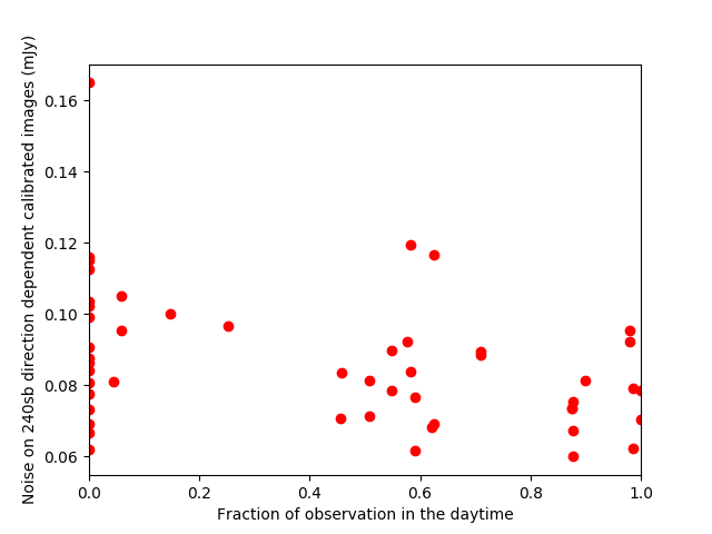
For the HBA band this has been demonstrated by the Survey Key Science project (the LoTSS survey), which makes use of both day/night-time observations, avoiding sunrise and sunset. The plots in figure 1 and 2 show how the rms of the images varies versus the fraction of the observations during daytime, for data treated with direction independent and direction dependent calibration respectively. These plots show how the level of the rms achieved for observations performed during daytime is comparable to the one obtained for observations performed during the night. This means that the level of accuracy in RFI editing and TEC calibration is good enough to achieve rms of the order of 0.1-0.06 mJy/beam at 150 MHz with the Dutch array at any time of the day except during dawn and dusk.

LBA
The noise statistics for the LBA band are much lower, but some information can be inferred from the project LC8_031 which is surveying the LBA sky.
Although the absolute TEC level is higher during the day, the variations in the ionosphere (dTEC) measured during daytime result to have lower magnitude (e.g. <+/-0.3 between core and RS509) when compared to night time (usually dTEC ~+/-0.5).
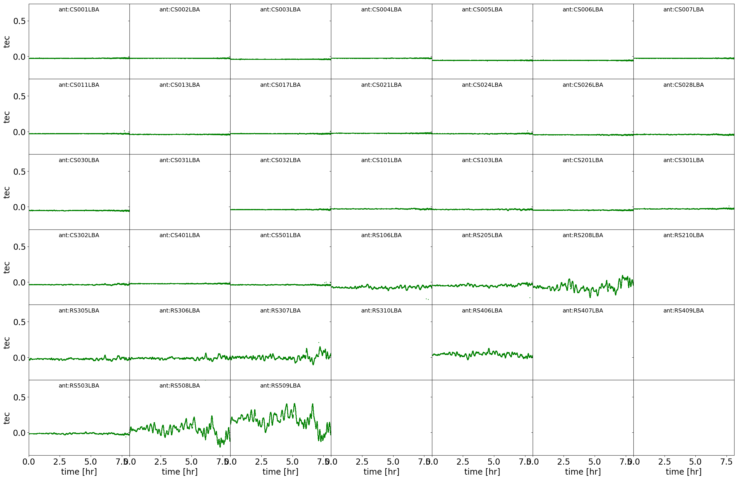
The ionosphere seems to have day-time oscillations typically faster than night-time ones of about a factor of 2, nevertheless:
- day-time oscillations seems to be more structured, as they are waves instead of instabilities (see figure 3 where multiple waves seems to overlap)
- amplitude scintillations appear to be suppressed during daytime
- If oscillations are structured (e.g. long TIDs), these are easier to solve and scintillation plays less of a problem. Because of the above evidences, we advise PI's to perform LBA observations during day-time avoiding dawn and dusk.
LBA sparse EVEN mode
In LBA_SPARSE mode half of the dipoles, distributed across the station, are used. This mode grants an intermediate performance between LBA_INNER (not offered in Cycle 16-19) and LBA_OUTER (offered in Cycles 16-19), with a suppression of the magnitude of the side-lobes compared to the latter. The effective size of the station is around 65 m, which provides a primary beam FWHM of 4.9 deg at 54 MHz.
Note that because of the ongoing commissioning activities, observing with this antenna mode is only enabled as a shared risk mode and only the mode 'SPARSE_EVEN' is made available. Although a suboptimal performance of stations CS031, CS302 is known because of old station calibration tables installed at these stations, the overall perfmance is good and high quality imaging can be performed with this mode.

In the following table, a summary of the performance of the system is reported, based on a number of commissioning observations to test the LBA_SPARSE_EVEN mode. Also, a comparison with LBA_OUTER is performed in order to provide proposers simple guidelines to make their antenna mode choices.