This section provides a brief overview of the LOFAR system and introduces some of the technical (and hardware) terms used throughout the rest of the documentation.
A simplistic diagram of the LOFAR signal path is shown in Figure 1: The radio signals enter the system through the antennas, which contain the first amplifier and, in the case of the High Band Antennas (HBA), an analogue true time delay beamformer (see Antennas for more details). The signal is then transported via coaxial cables to the station processing cabinet, which contains the digital Receiver Units (RCUs), the Remote Station Processing (RSP) boards, the Transient Buffer Boards (TBBs), and the local control unit (LCU). The LCU is a standard Linux PC that monitors and controls the local station hardware.
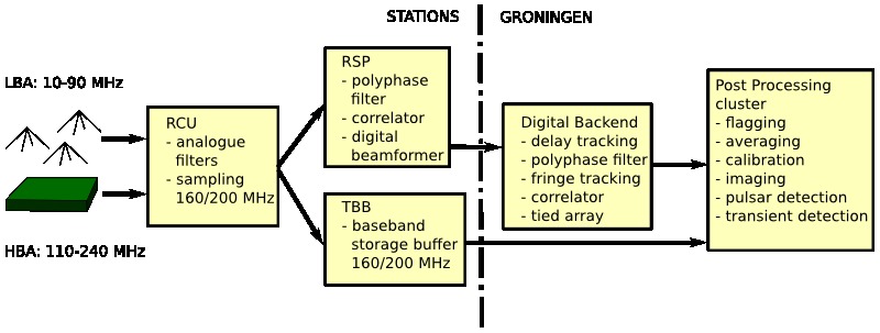
The RCUs have three single polarization inputs to connect either the HBAs or one of the Low Band Antennas (LBAs) to the RCU. There are analogue filters directly after the inputs: 10 MHz and 30 MHz high pass filters on the LBA input, as well as 110-190, 170-230, and 210-250 MHz bandpass filters on the HBA input. The LBA high pass filters are used to include (10 MHz) or suppress (30 MHz) the strong Earth-bound short wave radio signals below 30 MHz. The HBA band pass filters are used to select an appropriate Nyquist zone for a certain clock and observing frequency. Finally, the signal is digitized by a 12 bit analogue to digital converter (ADC) at a sampling frequency of 160 MHz (80 MHz total band width) or 200 MHz (100 MHz total band width). More details about the frequency setup can be found here .
The digitized signals can now proceed in parallel to two different pieces of hardware: the TBBs and the RSP boards. The TBBs contain memory buffers, which store the most recent 11 seconds of data from every RCU. The TBBs freeze and dump their contents if they receive a trigger, which may come from an algorithm running in real time on a field programmable gate array (FPGA) on the TBB. Alternatively, an explicit command to dump its contents right away can be given to the TBBs.
On the other hand, the RSP boards first split the input signals from the RCUs into 512 subbands via a polyphase filter (PPF) followed by a 1024 point, fast Fourier transform (FFT). Further processing is done per subband. The most common step after channel separation is the digital phase rotation beamformer, which sums the signals of all selected RCUs after multiplication with a complex phase factor representing the geometrical delay required for beamforming towards a certain direction, and a complex phase/amplitude calibration factor from the station calibration. The beam-formed signals are subsequently sent to the real-time digital backend in Groningen over the wide area network (WAN).
The RSP boards also implement a station correlator that can be used to obtain RCU-RCU visibilities for a single sub-band with integration times of multiples of one second. These visibilities can be used to image the entire sky at once, and image very large angular scale structures. This mode is extensively used for station calibration.
The real-time digital backend is now a Graphical Processing Unit (GPU)-based Cobalt system. It can perform delay compensation and fringe stopping on the incoming data streams from the stations, separate each subband into up to 256 channels using a PPF and and FFT, compensate for the bandpass of the station PPF, and correlate (interferometry) or add the signals of (subsets of) stations to form tied-array beams (Beam forming).
The minimum real time integration time is approximately 0.5 seconds. Normal observations will be done at a time resolution of multiples of 1.006633 seconds. Note that it is also possible to bypass all these operations and directly pass the input data streams to the storage- and post processing cluster. The minimum time resolution for tied-array operations is about 5.12 microsecond.
The real time digital backend is the final stage of the real time system. Its output data, as well as all TBB dumps, are stored on the post-processing cluster.
More detailed information on each of the stages of the signal path are available in van Haarlem et al. 2013 (http://arxiv.org/abs/1305.3550).