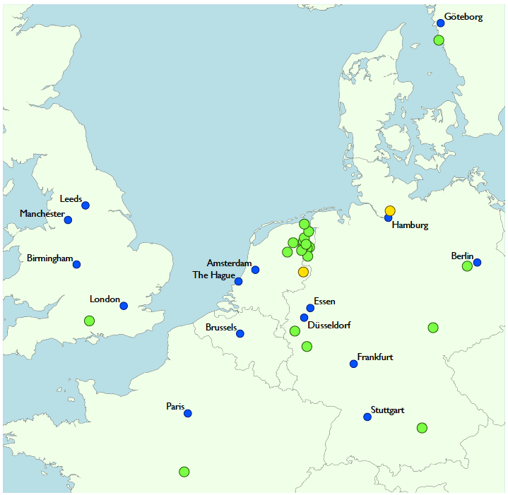
The fundamental receiving elements of LOFAR are two types of small, relatively low-cost antennas that together cover the 10–240 MHz operating bandpass. These antennas are grouped together into 52 separate stations distributed over the northeastern part of the Netherlands as well as in Germany, France, the UK, Sweden, Poland, Ireland, and Latvia.
An overview of the geographical location of the stations can be found here.
Station Naming
The names of the stations are selected such that CS in the name means that they have two HBA fields rather than one. They are located either directly in the core area or nearby.
The RS in a station name denotes a remote station with only one HBA field and it is located in the Netherlands.
For international stations the appropriate country code is used. The numbers in a station name are somewhat historic but are unique for a station.
Core Stations
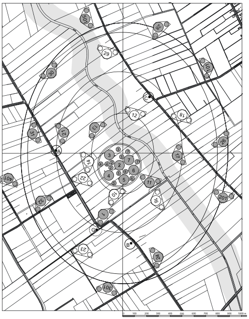
For the majority of the array located in the Netherlands, the geographic distribution of stations shows a strong central concentration with 24 stations located within a radius of 2 km referred to as the “core”. Within the core, the land was purchased to allow maximum freedom in choosing station locations. This freedom allowed the core station distribution to be optimized to achieve the good instantaneous uv coverage required by many of the Key Science Projects. At the heart of the core, six stations reside on a 320 m diameter island referred to as the “Superterp”; “terp” is a local name for an elevated site used for buildings as protection against rising water. These Superterp stations, shown in Figure 1, provide the shortest baselines in the array and can also be combined to effectively form a single, large station.

A layout of where all LOFAR Core Stations are located, is shown in Figure 2. More locations are prepared than actual stations are placed in this phase of LOFAR.
Remote Stations
Beyond the core, the 14 remaining LOFAR stations in the Netherlands are arranged in an approximation to a logarithmic spiral distribution. Deviations from this optimal pattern were necessary due to the availability of land for the stations as well as the locations of existing fiber infrastructure. These outer stations extend out to a radius of 90 km and are generally classified as “remote” stations. As discussed below, these remote stations also exhibit a different configuration to their antenna distributions than core stations. The full distribution of core and remote stations within the Netherlands is shown in Figure 3.

International Stations
14 international stations are currently operational. They are in Germany: Effelsberg (DE601), Unterweilenbach (near Garching/Munich, DE602), Tautenburg (DE603), Potsdam-Bornim (DE604), Jülich (DE605), Norderstedt (DE609), in the UK: Chilbolton (UK608), in France: Nançay (FR606), in Sweden: Onsala (SE607), in Poland: Borowiec (PL610), Lazy (PL611), Baldy (PL612), in Ireland (IE613) and in Latvia (LV614).
Current Status
There are 38 stations operational in the Netherlands (24 core and 14 remote stations) and 14 international stations operational in Germany (6), the UK (1), France (1), Sweden (1), Poland (3), Ireland (1) and Latvia (1).
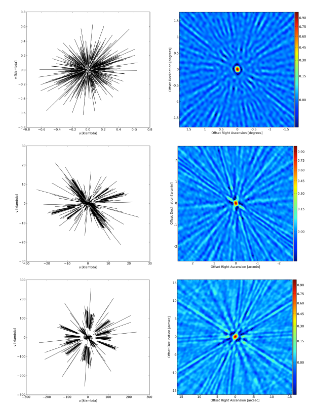
Example UV Coverages
Below, we show the sample uv coverage plots (left) and synthesized beams (right) including all present and planned LOFAR stations. The uv coverage is calculated for a source at declination 48 degrees and covers a 6 h track between hour angles of approximately -3 to +3 hours. One point is plotted every minute. Synthesized beams are calculated using uniform weighting and multi-frequency synthesis over the full LBA frequency range from 30 to 78 MHz. The top frames are for the 24 core stations only, middle frames include all 40 core and remote stations, and the bottom frames include all 50 core, remote, and international stations.

The Figure below illustrates the instantaneous uv coverage (near transit at the same declination) for the same complement of stations and shows the effect of the full 48 MHz bandwidth from 30 to 78 MHz on the uv coverage. In the left frames, one point is plotted every 0.2 MHz.