A number of different types of beam are used when dealing with the LOFAR telescope. LOFAR beam-forming is hierarchical in nature - forming first beams at HBA tile level, then station level, and then array level - so the picture can be confusing if one is not completely clear on what `beam' is meant in a particular situation.
Dipole and Tile Beams
LBA antennas are sensitive to the entire visible sky, so the LBA 'dipole beam' covers the entire sky, but with a significant drop in sensitivity below about 30° elevation.
Each HBA tile contains 4x4 antennas which are combined with an analogue beam former before the data are sent to the station processor (RSP) boards. Each tile is therefore sensitive to a smaller portion of the sky. This 'tile beam', sometimes called the 'analogue beam', has a FWHM beam width of 30-15 deg over the frequency range 110-240 MHz.
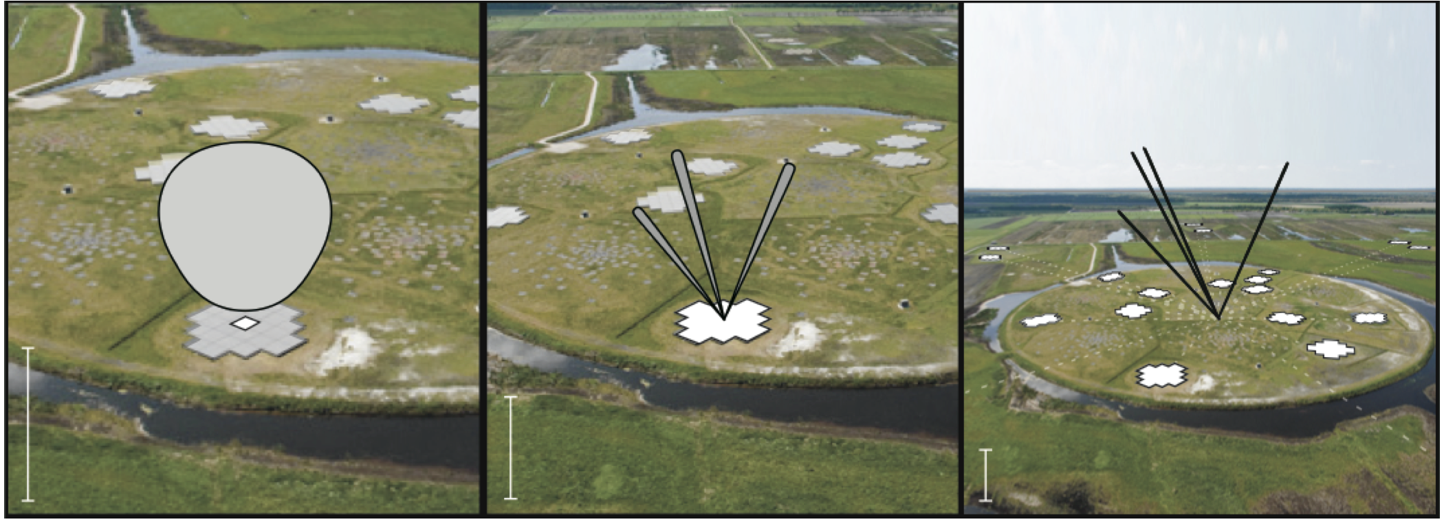
Station Beam or Sub-Array Pointing (SAP)
A 'station beam', also known as a 'sub-array pointing' (SAP) is formed by combining, with the appropriate phase-rotation, all the selected LBA antennas or HBA tiles (formally the signals of the all selected RCUs) in a given station to form a beam towards a specified direction.
Beam-forming is done independently for each subband and the resulting beam of each subband is referred to as a "beamlet". Multiple beamlets with the same pointing position are summed to produce beams with a larger bandwidth. Thus the available bandwidth (up to 488 subbands in 8-bit mode) has to be distributed over all the specified station beams. Therefore, if 8 station beams are specified with equal subbands, the total number of subbands per individual station beam should not be more than 61. Although it is theoretically possible to create as many station beams as there are subbands, large numbers of station beams become impractical to set up. It is therefore recommended that no more than 8 station beams should be created. Beams are calculated once per second, resulting in a gain variation of 0.3% for a station beam of 3 deg in diameter.
After forming a station beam towards a specified direction (say all 488 subbands in one SAP), the data flows to the CEP to be processed by the correlator.
Tied-Array Beams (TABs)
Each SAP returned from multiple core stations can be combined coherently to form multiple tied-array beams, each with a different pointing direction within the overall station beam but covering the same range of subbands as the SAP.
A large number of TABs can be formed, limited by the computation and processor load on the correlator and ability to keep up with data writing to disk. In practice this means that the total number of TABs which can be formed depends upon the number of subbands (across all SAPs) and the number of stations used. For example, 222 TABs can be formed using 161 subbands and the six superterp stations, or 171 TABs can be formed using 258 subbands and 24 core stations. Both examples are Stokes I only and near the limits of the current system. If all Stokes parameters are desired, then the total number of TABs possible in each of these examples would need to be divided by four.