In Shimwell et al. (2022) we present LoTSS-DR2. In this data release from the ongoing LOw-Frequency ARray (LOFAR; van Haarlem et al. 2013) Two-metre Sky Survey (LoTSS; Shimwell et al. 2017, 2019) we present 120-168 MHz images covering 27% of the northern sky. Our coverage is split into two regions centred at approximately 12h45m +44◦30′ and 1h00m +28◦00′ and spanning 4178 and 1457 square degrees respectively. The images were derived from 3,451 hrs (7.6 PB) of LOFAR High Band Antenna data which were corrected for the direction-independent instrumental properties as well as direction-dependent ionospheric distortions during extensive, but fully automated, data processing. A catalogue of 4,396,228 radio sources is derived from our total intensity (Stokes I) maps, where the majority of these have never been detected at radio wavelengths before. At 6′′ resolution, our full bandwidth Stokes I continuum maps with a central frequency of 144 MHz have: a median rms sensitivity of 83 μJy/beam; a flux density scale accuracy of approximately 10%; an astrometric accuracy of 0.2′′; and we estimate the point-source completeness to be 90% at a peak brightness of 0.8 mJy/beam. By creating three 16 MHz bandwidth images across the band we are able to measure the in-band spectral index of many sources, albeit with an error on the derived spectral index of > ±0.2 which is a consequence of our flux-density scale accuracy and small fractional bandwidth. Our circular polarisation (Stokes V) 20′′ resolution 120-168 MHz continuum images have a median rms sensitivity of 95 μJy/beam, and we estimate a Stokes I to Stokes V leakage of 0.056%. Our linear polarisation (Stokes Q and Stokes U) image cubes consist of 480 × 97.6 kHz wide planes and have a median rms sensitivity per plane of 10.8 mJy/beam at 4′ and 2.2 mJy/beam at 20′′; we estimate the Stokes I to Stokes Q/U leakage to be approximately 0.2%. The Stokes I, Q, U and V images and calibrated uv-data are all publicly released to facilitate the thorough scientific exploitation of this unique dataset.
Observations & Processing
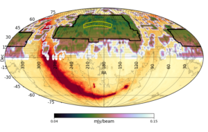
As shown in Fig. 1, LoTSS-DR2 consists of 841 pointings and it covers a total of 5634 square degrees which corresponds approximately to our contiguous coverage at the time of beginning the LoTSS-DR2 processing run. The data release is formed by two contiguous regions that are centred at approximately 12h45m00s +44◦30′00′′ (RA-13 region) and 1h00m00s +28◦00′00′′ (RA-1 region) and span 4178 and 1457 square degrees, or 626 and 215 pointings, respectively. The data were taken between 2014-05-23 to 2020-02-05 as part of the LoTSS projects LC2_038, LC3_008, LC4_034, LT5_007, LC6_015, LC7_024, LC8_022, LC9_030, LT10_010 and the co-observing projects LC8_014, LC8_030, DDT9_001, LC9_011, LC9_012, LC9_019, LC9_020, COM10_001, LC10_001, LC10_010, LC10_014, LT10_012, LC11_013, LC11_016, LC11_019, LC11_020, LC12_014. All the data that were processed as part of this data release are stored in the LOFAR Long Term Archive (LTA) with approximately 62% in Forschungszentrum Jülich, 32% in SURF8and the remaining 6% in Poznan. The vast majority of pointings were observed for a total of 8 hrs with 48 MHz (120-168 MHz) of bandwidth which allows for two pointings to be observed simultaneously with current LOFAR capabilities. However, primarily due to the co-observing program10 through which we exploit the multi-beam capability of LOFAR and accumulate LoTSS data simultaneously with observations conducted for other projects, for 18 of the pointings in LoTSS-DR2 we have used data that has the same frequency coverage but a total integration time of ∼16 hrs. The overall observing time utilised for this data release is 3451 hrs and the volume of archived data that was processed is 7.6 PB. Thus the average data size for an 8 hr pointing (two observed simultaneously) is 8.8 TB but there is significant variation because data that have been recorded since 2018-09-11 are typically five times smaller than those before this date due to Dysco compression (Offringa 2016) being utilised by the radio observatory prior to ingesting data into the LTA in more recent observations.
Fig. 1. The status of the LoTSS observations as of April 2021 and the approximate current sensitivity coverage (accounting for station projection and typical sensitivities achieved to date) overlaid on the Haslam et al. (1982) 408 MHz all-sky image (corresponding to yellow to deep red colours, with associated contours). The yellow and black outlines show the LoTSS-DR1 and LoTSS-DR2 areas respectively and the small black dots show the 3168 LoTSS grid positions. LoTSS-DR1 included 63 pointings, LoTSS-DR2 includes 841 pointings; we have fully observed 1623 pointings including those of DR2, a further 154 pointings are partly observed and observations still need to be conducted for 1391 pointings to complete the survey.
To process the data they are first ‘staged’ in the LTA; staging is the procedure of copying data from tape to disk and is necessary to make the large archived datasets available for transfer to a compute cluster. The data are then processed with a direction independent (DI) calibration pipeline that is executed on compute facilities at Forschungszentrum Jülich and SURF (see Mechev et al. 2017 and Drabent et al. 2019). These compute clusters are connected to the local LTA sites with sufficiently fast connections to mitigate the difficulties that would be experienced if we were to download these large datasets to external facilities. Unfortunately data transfer issues are not yet fully mitigated as we currently do not process data on a compute cluster local to the Pozna ́n archive and instead we copy these data (6% of LoTSS-DR2) to Forschungszentrum Jülich or SURF for processing.
The DI calibration pipeline used for this data processing follows the same procedure as that used in LoTSS-PDR and LoTSS-DR1 (Shimwell et al. 2019). This method is described in van Weeren et al. (2016) and Williams et al. (2016) and makes use of several software packages including the Default Pre-Processing Pipeline (DP3; van Diepen, Dijkema, & Offringa 2018), LOFAR SolutionTool (LoSoTo; de Gasperin et al. 2019) and AOFlagger (Offringa, van de Gronde, & Roerdink 2012). The pipeline corrects for direction independent errors such as the clock offsets between different stations, ionospheric Faraday rotation, the offset between XX and YY phases and amplitude calibration solutions (see de Gasperin et al. 2019 for a detailed description of these effects). The Scaife & Heald (2012) flux density scale is used for the amplitude calibration and we use TGSS-ADR1 sky models of our target fields for an initial phase calibration, although both the amplitude and phase calibration are refined during subsequent processing. For regular LoTSS processing we have set up the pipeline to reduce the data volume, typically by a factor of 64 by averaging both in time and frequency. This is because the archived LoTSS data typically have a frequency resolution of 16 channels per 0.195 MHz subband and a time resolution of 1 s to facilitate future studies with the international LOFAR stations as well as spectral and time dependent studies, but such high time and frequency resolution data is not required for 6′′ imaging. During the DI calibration the data are therefore averaged to a frequency resolution of 2 channels per 0.195 MHz subband and a time resolution of 8 s.
Once the DI calibration pipeline is complete, the smaller, more averaged, output datasets can be downloaded to other compute clusters for further processing with a more computationally expensive direction dependent (DD) calibration and imaging pipeline13. The DD routine is an improvement upon that used in LoTSS-DR1 and again makes use of kMS (Tasse 2014 and Smirnov & Tasse 2015) for direction dependent calibration, and of DDFacet (Tasse et al. 2018) to apply the direction dependent solutions during imaging. Compared to LoTSS-DR1, the most significant changes are the fidelity of faint diffuse emission and the increased dynamic range. The LoTSS-DR2 DD pipeline and its performance are described in detail in Tasse et al. (2021); however, for completeness we briefly summarise the procedure below.
We begin the processing with just a quarter of the DI calibrated channels (spaced across the frequency coverage) by creating a wide-field (8.3◦ × 8.3◦) image. Using the resulting sky model we revise the direction independent calibration and tessellate the field into 45 different directions. The recalibrated data are imaged to update the sky model, and with the new model, calibration solutions are derived towards each of the 45 directions simultaneously. Then, we image the wide-field again but this time applying the phase corrections from the direction dependent calibration solutions which allows us to produce a further improved sky model. Here we perform an initial refinement of the flux density scale through the bootstrap procedure described by Hardcastle et al. (2016), which was also used in the LoTSS-DR1 processing. The flux density scale is further refined during mosaicing but this initial refinement helps ensure emission is described by a power-law which aids the deconvolution. Direction dependent calibration solutions are again derived from the up-to-date sky model and this time both the amplitude and phase are applied in the subsequent imaging step. Using these solutions, together with the updated sky model, we predict the apparent direction-independent view of the sky and perform a further direction-independent calibration step using that model and a further imaging step. All the data are then included for the first time and direction-independent followed by direction-dependent calibration solutions are derived using the latest sky model. The data are then imaged again, and further direction-dependent calibration solutions are derived from the resulting sky model before the final imaging steps are conducted with the latest calibration solutions.
The final imaging steps result in: (i) full-bandwidth high (6′′) and low (20′′) resolution Stokes I images; (ii) three 16 MHz bandwidth high (6′′) resolution Stokes I images with central frequencies of 128, 144 and 160 MHz; (iii) Stokes Q and U low (20′′) and very low (4′) resolution undeconvolved image cubes with a frequency resolution of 97.6 kHz; (iv) and a Stokes V full-bandwidth low (20′′) resolution undeconvolved image. Here only Stokes I products are deconvolved due to the deconvolution capabilities of DDFacet at the time of processing. Once the data are processed, the final products are archived and an automated quality assessment of the image is conducted to assess the astrometry, flux density scale accuracy and noise level.
Some notable aspects of the DD pipeline processing include the improvement of the astrometric accuracy of the final high resolution Stokes I images by performing a facet-based astrometric alignment (as in LoTSS-DR1) with sources in the the Pan-STARRS optical catalogue (Flewelling et al. 2020) and applying appropriate shifts when imaging (see Shimwell et al. 2019). To deconvolve thoroughly, throughout the processing we refine the masks used for deconvolution, we also continuously propagate previously derived deconvolution components to subsequent imaging steps to avoid having to fully deconvolve at each imaging iteration, and we regularise the calibration solutions to effectively reduce the number of free parameters that are applied when imaging. Moreover, as characterised in Sect. 3.3 of Shimwell et al. (2019) and detailed in Tasse et al. (2018), by using a facet-dependent point spread function we account for time-averaging and bandwidth-smearing effects (e.g. Bridle & Schwab 1999) for deconvolved sources, this would otherwise be significant (a ∼ 30% reduction in peak brightness at a distance of 2.5◦ from the pointing centre) when imaging at 6′′ with 2 channels per 0.195 MHz subband and a time resolution of 8 s. Finally, we note that the restoring beam used in DDFacet for each image product type is kept constant over the data release region and that all image products are made with a uv-minimum of 100 m with the uv-maximum varied to provide images at different resolutions - the highest resolution 6′′ images use baselines up to 120km (i.e. all LOFAR stations within the Netherlands).
The DD calibration has been primarily conducted on the LOFAR-UK compute facilities14 hosted at the University of Hertfordshire, but a small fraction of processing was also carried out on the Italian LOFAR computing facilities and compute clusters at Leiden University and the University of Hamburg. The DI and DD processing, as well as the observational status and quality indicators are all kept track of in central MySQL databases which are updated during the data processing. This allows us to easily coordinate automated processing across many different compute clusters with minimal user interaction
The mosaicing and cataloguing follow the same procedure as used for LoTSS-DR1 which is described in Shimwell et al. (2019). This implies a mosaic is produced for each pointing by reprojecting all neighbouring pointing images onto the same frame as the central pointing and averaging together the images using weights equal to the station beam attenuation combined with the image noises. Poorly calibrated facets, which are generally caused by severe ionospheric or dynamic range effects, are identified in each image as those with larger than 0.5′′ astrometric errors (derived from cross matching with Pan-STARRS) and these regions are blanked in the individual pointing images prior to mosaicing. On average this results in 15±22% of the pixels within 30% of the primary beam power level being excluded for a given pointing. Unlike in LoTSS-DR1, we further refine the flux density scale of the images during the mosaicing procedure by applying the method that is described in Sect. 3.3 of Shimwell et al. (2022). Sources are detected on the mosaiced images using PYBDSF (Mohan & Rafferty 2015) with wavelet decomposition and a 5σ peak detection and 4σLN threshold to define the boundaries of source islands, where σLN is the local background noise. During source detection, PYBDSF characterises emission with Gaussian components which are automatically combined into distinct sources to create the source catalogue. This automated association of Gaussian components into final sources is limited because of various reasons such as the complexity and the extent of the source structures, the angular separation between components of the emission related to the same source, and the entanglement of emission from distinct objects. As described in Sect. 5.1 of Shimwell et al. (2022), our attempts to refine the PYBDSF catalogues through source association/deblending, and cross-identification with optical/infrared (e.g. Williams et al. 2019 and Kondapally et al. 2021) are ongoing.
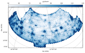
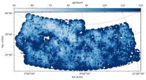
The mosaic images, and catalogues derived from them, have significant overlap so when producing the final full-area catalogue we remove duplicate sources by only keeping those in a given mosaic if they are closest to the centre of that particular mosaic. Our final full-area catalogue consists of 4,396,228 radio sources made up of 5,121,366 Gaussian components. The overall sensitivity distribution is shown in Fig. 2.


